216
JOHNSON CONTROLS
FORM 201.21-NM3 (616)
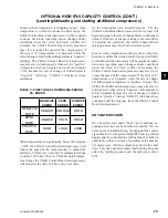
OPTIONAL HIGH IPLV CAPACITY CONTROL (CON'T)
(Loading/Unloading and starting additional compressors)
With 2 compressors now running and a current VSD
frequency of 115 HZ, the start frequency will be
computed as:
115 Hz x (2-1) = 115 = 58 Hz
2
2
When the compressors restart, loading and unloading is
inhibited for 30 seconds after the compressor(s) reaches
the start frequency, as is the case on any compressor start.
The anti-recycle timer will be set to 120 sec.
In a situation where a single compressor on a 2 com-
pressor chiller is running and is in load limiting for any
reason, and LCHLT > Se CR for < 5 minutes,
but > 30 seconds, the micro will reset the load/unload
timers to 2 seconds every “potential” load cycle. When
LCHLT > Se CR for > 5 minutes, the micro will
enable the lag compressor just as it were not satisfied and
determine a second compressor was required to handle
the load, since the lead compressor is load limited.
If the cooling capacity exceeds the demand (LCHLT
< Setpoint – CR/2) and multiple compressors are
operating, the Chiller Control Board microprocessor
will decrease the speed of the compressors at the rate
of 0.1-1 Hz every 2 seconds until the LCHLT rises to
within the control range. If temp remains below Setpoint
– CR/2, rate is falling, and speed falls to the minimum
VSD frequency as determined by the ambient, the VSD
will decelerate all compressors to 5 Hertz. The last lag
compressor will be shut down. The remaining compres-
sors will be restarted minus the lag compressor. The
lead compressor will restart and accelerate to the STOP
COMP FREQ designated as:
STOP
= Minimum VSD Freq x (Number of Compressors R1)
COMP FREQ
Number of Compressors Running
In this example: Number of compressors running = 1
Minimum VSD Freq.= 50 Hz
In the example above, one compressor will restart at 100
Hz as indicated in the formula below:
50Hz x (1+1) = 100 Hz
1
The load timer will also be set to 30 seconds and the
unload timer will be set to 10 seconds.
On 3 and 4 compressor chillers, if temperature stays
below the Setpoint minus the Control Range/2,
another lag compressor will be shut down using the
same guidelines.
When the system is only operating a single (lead)
compressor, if temperature continues to stay below the
control range (Setpoint – CR), the Chiller Control Board
microprocessor will unload the compressor at the rate
of 1Hz every 2 seconds. This will continue until the
frequency drops below the Minimum VSD Frequency
determined by the ambient temperature. At this point,
the lead compressor will be shut down.
FUZZY LOGIC CONTROL
The fuzzy logic control in software makes deci-
sions to load or unload according to the error or
deviation from Setpoint, and the rate of change of
chilled liquid temperature. Before making a change in
speed, the logic will look at the load and unload tim-
ers to assure they are timed out. It also looks to assure
there is no load limiting in effect. Each time a change
is made, the incremental change in speed is still 0.1-1
Hz, unless temperatures fall near the leaving chilled
liquid cutout.
In most situations, when the chilled liquid temperature
is above the Se CR, the Chiller Control Board
microprocessor will continue to increase the speed of
the compressor(s) to load the chiller until temperature
drops in the general range of the Setpoint High Limit.
As the temperature drops and approaches the Setpoint
High Limit (Se CR), the micro’s fuzzy logic will
begin factoring in the rate of change before continuing to
load. If the rate of change is dropping too fast and there
is potential for overshoot, the Chiller Control Board
microprocessor may elect not to continue to increase
speed.
OPERATION
Summary of Contents for YCAV0267E
Page 61: ...61 JOHNSON CONTROLS FORM 201 21 NM3 616 This intentionally left blank 6 ...
Page 73: ...73 JOHNSON CONTROLS FORM 201 21 NM3 616 This page intentionally left blank 6 ...
Page 89: ...89 JOHNSON CONTROLS FORM 201 21 NM3 616 6 035 20890 009 REV LOCATION LABEL CON T LD11141 ...
Page 146: ...146 JOHNSON CONTROLS FORM 201 21 NM3 616 TECHNICAL DATA This page intentionally left blank ...
Page 147: ...147 JOHNSON CONTROLS FORM 201 21 NM3 616 6 This page intentionally left blank ...
Page 247: ...247 JOHNSON CONTROLS FORM 201 21 NM3 616 This page intentionally left blank ...
Page 269: ...269 JOHNSON CONTROLS FORM 201 21 NM3 616 This page intentionally left blank 8 ...
Page 289: ...289 JOHNSON CONTROLS FORM 201 21 NM3 616 8 This page intentionally left blank ...
Page 317: ...317 JOHNSON CONTROLS FORM 201 21 NM3 616 8 This page intentionally left blank ...
Page 348: ...348 JOHNSON CONTROLS FORM 201 21 NM3 616 MAINTENANCE NOTES ...
Page 349: ...349 JOHNSON CONTROLS FORM 201 21 NM3 616 9 NOTES ...

