24
YORK INTERNATIONAL
should be released and the leaks repaired. If not, raise
the system pressure to approximately 150 PSIG by in-
troducing dry nitrogen. The dry nitrogen cylinder must
be equipped with a pressure regulating valve set at 150
PSIG for this procedure. If any apparent leakage should
develop during this procedure, the pressure should be
removed and the leaks repaired before raising the sys-
tem pressure further. The dry nitrogen cylinder should
be disconnected as soon as the pressure within the sys-
tem has been raised to the desired maximum. Then the
system should be thoroughly and carefully tested in the
conventional way with a leak detector used in accor-
dance with the manufacturers instructions.
CHARGING CONNECTIONS
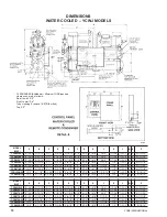
The seal capped refrigerant liquid stop valve (see Dl-
MENSIONS) is provided with a capped port through which
refrigerant may be charged into the system. This port is
closed when the stem of the valve is screwed all the way
toward the open or back-seated position, and opens as
the stem is moved toward the closed position.
A length of copper tubing equipped with flare connec-
tions may be used as a charging connection. The charg-
ing connection may be attached to a refrigerant cylinder,
an absolute pressure gauge and charging panel, or a
vacuum pump as required for evacuating the system or
charging it with refrigerant. A dry nitrogen cylinder (with
its pressure regulating valve) may be connected by
means of a tee into the charging connection for conven-
ience during the testing procedure.
Refrigerant charging connections should either be evacu-
ated with the system piping or be purged of air by blow-
ing a small quantity of refrigerant through them.
VACUUM DEHYDRATION
NOTE: The operating of hermetic compressors in a
vacuum may damage the motor and cause it to
fail immediately or within a short time. For this
reason the compressor should never be oper-
ated during the evacuation procedure.
Dehydration, or removal of water or moisture from the
refrigerant system after installation has been completed,
may be accomplished readily by the evacuation method.
This method consists basically of applying a deep vac-
uum to the refrigerant-containing portions of the system
after the system has been thoroughly leak tested and
made tight. During the evacuation procedure, as the pres-
sure within the system is reduced, the boiling (or vapor-
izing) point of any water or moisture within the system is
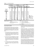
also reduced as shown by TABLE 1.
It should be noted, that under unusual circumstances, a
possibility exists for freezing water inside the system.
Such moisture or free water may be removed by the
Double Evacuation procedure as explained in Paragraph
4 of EVACUATING PROCEDURE.
STANDARDS To be considered dry and free of mois-
ture a refrigerant system must be capable of sustaining
a pressure of .019 lb. per sq. in. absolute, or (1000 mi-
crons) absolute pressure, or better, as shown by TABLE
1 with the vacuum pump valved off. This is equivalent to
29.882 in. vacuum gauge pressure and to a boiling point
of water of 1°F. This condition may be considered satis-
factory for standard moisture evacuation purposes for
field-erected refrigerant systems.
VACUUM PUMP, COMPRESSOR AND MOTOR A
good quality vacuum pump capable of creating a vac-
uum of less than 1000 microns, or 1 mm of mercury
absolute pressure is necessary. THE COMPRESSOR
MUST NEVER BE USED FOR THIS PURPOSE.
ABSOLUTE PRESSURE GAUGE It is not satisfac-
tory nor accurate to attempt to read pressures in the
range of the required 29.882 inches of vacuum with an
ordinary compound gauge for several reasons. First, as
shown by TABLE 1, it is necessary to be able to read
very closely the increments of pressure below 28.94"
vacuum (78°F), at which point, moisture removal may
only be starting. Lower readings in small increments are
necessary as shown, and it is not possible to make them
accurately with the ordinary gauge. Second, these gauges
quickly lose calibration and become inaccurate. Third,
to be of value, the gauge pressure readings, even if ac-
curate, would have to be corrected in terms of the baro-
metric pressure at the time and location at which the
reading is taken. (Standard Tables of pressure and boil-
ing points of water are made up in terms of atmospheric
pressure at sea level or 14.696 PSIA as shown.)
The absolute pressure gauge is unaffected by baromet-
ric pressure and readings may be taken quickly and ac-
curately.
Instead of indicating how far the system pressure is be-
low atmospheric, as would a compound service gauge,
these devices indicate how far this pressure is above a
perfect vacuum.
For convenience in reading, these gauges are graduated
to read absolute pressure in microns or in millimeters of
mercury. Equivalent boiling points of water and gauge
pressures in inches vacuum are shown in TABLE 1. Note
that one millimeter of mercury is equal to 1000 microns.
It is recommended that a good quality absolute pres-
sure gauge be used in accordance with the
Manufacturers instructions. Recommended gauges are
the Zimmerli Absolute Pressure Gauge, the Stokes
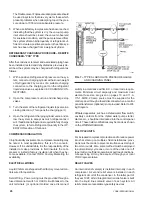
McLeod Gauge or the Meriam closed end U-tube type.
The latter gauge is illustrated by Fig. 7.
Summary of Contents for YCRJ45E00
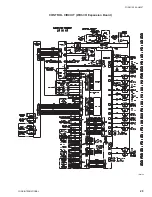
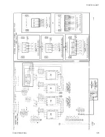
Page 29: ...FORM 150 24 NM27 YORK INTERNATIONAL 29 CONTROL CIRCUIT With I O Expansion Board LD02106 ...
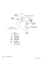
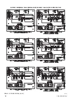
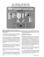
Page 30: ...30 YORK INTERNATIONAL FIG 9 SYSTEM WIRING ...
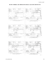
Page 31: ...FORM 150 24 NM27 YORK INTERNATIONAL 31 LD02678 ...
Page 35: ...FORM 150 24 NM27 YORK INTERNATIONAL 35 LD02679 ...
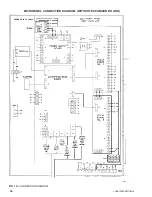
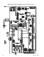
Page 36: ...36 YORK INTERNATIONAL MICROPANEL CONNECTION DIAGRAM With I O Expansion Board LD02107 ...
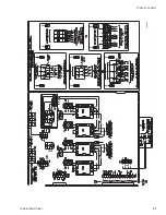
Page 37: ...FORM 150 24 NM27 YORK INTERNATIONAL 37 LD02108 ...

