26
YORK INTERNATIONAL
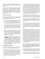
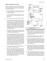
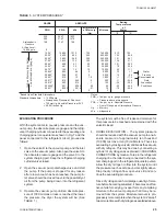
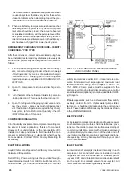
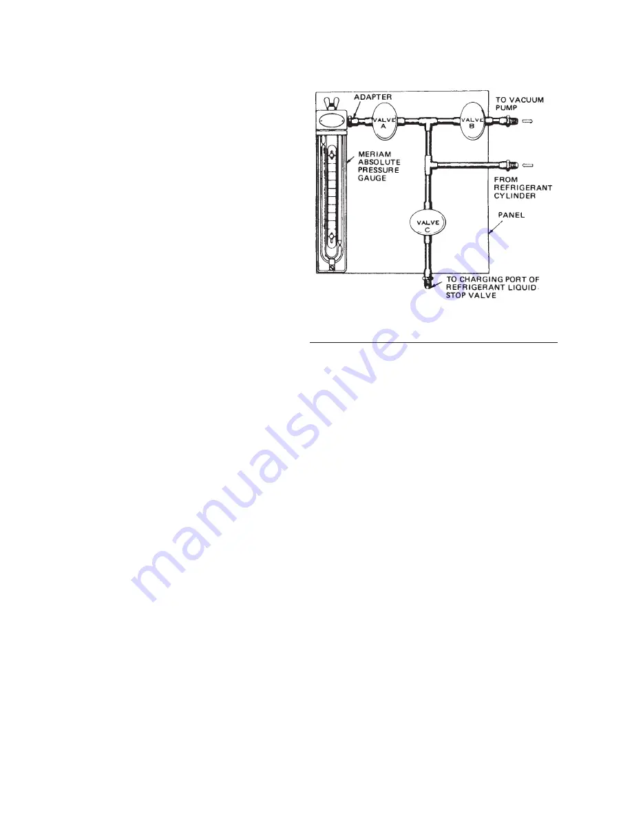
FIG. 7
TYPICAL ABSOLUTE PRESSURE GAUGE
AND CHARGING PANEL
The Double or even Triple evacuation procedure should
be used in systems that are very wet or those which
present problems when attempting to pull the pres-
sure down to 1000 microns absolute pressure.
5. When a satisfactory low pressure has been reached,
indicating that the system is dry, the vacuum pump
inlet valve should be closed, the vacuum observed
for sustained condition, and the pump removed from
the system after an initial quantity of refrigerant suf-
ficient to create a positive pressure in the entire sys-
tem has been charged from a weighed cylinder.
REFRIGERANT CHARGING PROCEDURE REMOTE
CONDENSER-YCR TYPE
After the condenser, receiver and associated piping have
been installed, tested and dehydrated as previously de-
scribed, the system may be charged with refrigerant as
follows:
1. With a positive Refrigerant-22 pressure on the sys-
tem, connect a charging cylinder with a known weight
of Refrigerant-22 by means of a suitable charging
connection to the charging port on the refrigerant
liquid stop valve as explained in CHARGING CON-
NECTIONS.
2. Open the compressor suction and discharge stop
valves.
3. Turn the stem of the refrigerant liquid stop valve in a
closing direction. (This opens the charging port.)
4. Open the refrigerant charging cylinder valve and al-
low the system to accept as much refrigerant as it
will. If additional refrigerant is required to fully charge
the system, refer to Refrigerant Quantity in the OP-
ERATION section of this book.
COMPRESSOR INSULATION
In high humidity environments, compressor sweating may
be noted. In most applications, this is of no concern.
However, if it is undesirable, it is the responsibility of the
installer to make provisions to field insulate the com-
pressor or install a factory insulation kit when they be-
come available. Contact YORK Factory Marketing for
availability.
ELECTRICAL WIRING
Liquid Chillers are shipped with all factory mounted con-
trols wired for operation.
Field Wiring Power wiring must be provided through a
fused disconnect switch or HACR circuit breaker to the
unit terminals (or optional molded case disconnect
switch) in accordance with N.E.C. or local code require-
ments. Minimum circuit ampacity and maximum dual
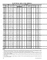
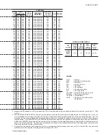
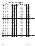
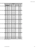
element fuse size are given on pages 10 and 11. A
115-1-60/50, 20 amp source must be supplied for the
control panel through a fused disconnect when a control
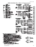
panel transformer (optional) is not provided. Refer to Wir-
ing Diagram.
Affiliated apparatus, such as a chilled water flow switch,
auxiliary contacts from the chilled water pump starter,
alarms, etc., should be interlocked into the control panel
circuit. These field modifications may be made as shown
on the WIRING DIAGRAM.
MULTIPLE UNITS
For increased compressor protection and to reduce power
inrush at start-up on multiple chiller installations, provi-
sions must be made to prevent simultaneous startup of
two or more units. Also, some method must be employed
to automatically cycle one or more of the units on or off
to permit more efficient operation at part load conditions.
A sequencing kit may be acquired through your local
YORK representative.
RELIEF VALVES
An internal relief valve(s) is installed internally in each
compressor. A second relief valve is installed in each
refrigerant circuit of the condenser. In the latter part of
the year 1997, a third integral internal relief valve is built
into the liquid line solenoid valve of each system. All
relief valves are resealable type safety devices.
LD02352
Summary of Contents for YCRJ45E00
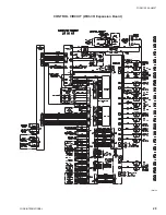
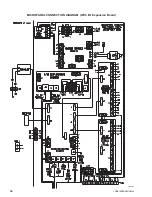
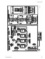
Page 29: ...FORM 150 24 NM27 YORK INTERNATIONAL 29 CONTROL CIRCUIT With I O Expansion Board LD02106 ...
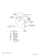
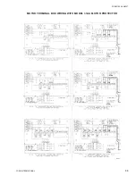
Page 30: ...30 YORK INTERNATIONAL FIG 9 SYSTEM WIRING ...
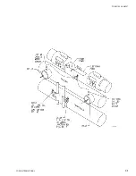
Page 31: ...FORM 150 24 NM27 YORK INTERNATIONAL 31 LD02678 ...
Page 35: ...FORM 150 24 NM27 YORK INTERNATIONAL 35 LD02679 ...
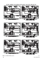
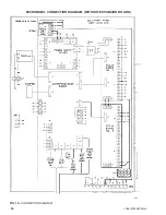
Page 36: ...36 YORK INTERNATIONAL MICROPANEL CONNECTION DIAGRAM With I O Expansion Board LD02107 ...
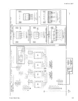
Page 37: ...FORM 150 24 NM27 YORK INTERNATIONAL 37 LD02108 ...

