FORM 150.24-NM27
YORK INTERNATIONAL
95
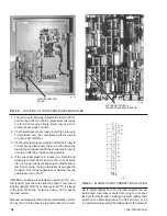
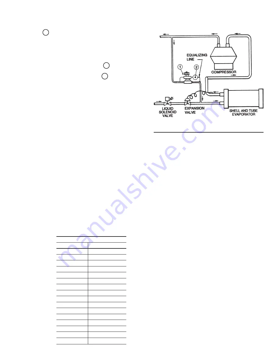
2. Adjust the pilot power assembly adjustment screw
2 to approximately the middle of its adjustment
range.
3. The chiller must be running and stabilized on the
minimum stage capacity. In establishing this condi-
tion, it may be necessary to deactivate the regulator
by de-energizing the solenoid 1 .
4. Adjust the adjustment screw 2 in the clockwise
direction to open the valve at a higher pressure
(sooner) or in the counterclockwise direction to open
the valve at a lower pressure (slower response). The
valve is feeding when the valve outlet feels warm to
the touch.
The adjustment is correct when system suction pres-
sure rises to a point nearly equal to normal running
pressure at the midpoint in the Control Zone.
5. Further minor adjustment may be necessary to be
certain that the valve opens fully before the tempera-
ture point at which the compressor stops due to a
fall in Return or Leaving Water Temp.
6. Repeat this procedure on the other system.
NOTE: HOT GAS should not be considered as an addi-
tional step of unloading when programming the
number of steps of loading/unloading.
FIELD INSTALLATION
If it becomes necessary to field install the Hot Gas
(Loadminder) Option, two kits are required. Order the kit
from Table 3.
TABLE 3
KIT, HOT GAS BYPASS
MODEL
PART NO.
YCWJ45EE
375-05358-001
YCWJ55HE
375-05358-001
YCWJ56HF
375-05358-001
YCWJ66KH
375-05358-001
YCWJ67KH
375-05358-002
YCWJ77KH
375-05358-003
YCWJ88MH
375-05358-003
YCWJ99MJ
375-05358-004
YCRJ45E0
375-05886-001
YCRJ55H0
375-05886-001
YCRJ56H0
375-05886-001
YCRJ66H0
375-05886-001
YCRJ67K0
375-05886-002
YCRJ77K0
375-05886-002
YCRJ88M0
375-05886-003
YCRJ99M0
375-05886-004
In addition, a 471-01232-101 kit must also be ordered.
The 471-01232-101 kit consists of a second Relay Out-
put Board. It is not required if two Relay Boards are al-
ready installed in the control panel.
DISCHARGE PRESSURE READOUT OPTION
The Discharge Pressure Read-out Option P/N 471-
01266-131 allows the user to obtain control panel dis-
plays of discharge pressure. Additionally, other displays
such as fault information will then hold relevant discharge
pressure information useful in diagnosing problems.
The discharge pressure unloading feature also becomes
usable when this option is installed (Page 52) as well as
fan cycling by discharge pressure.
The kit consists of discharge pressure transducers for
each system, wire harnesses, and associated mounting
hardware.
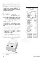
LOCAL PRINTER OPTION
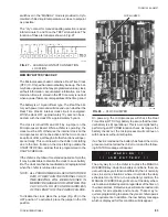
The Micro Panel is capable of supplying a print-out of
chiller conditions or fault shutdown information at any
given time. This allows operator and service personnel
to obtain data and system status with the touch of the
keypad. In addition to manual print selection, the micro
panel will provide an automatic print-out whenever a fault
occurs. An explanation of the keypad use to obtain a
print-out is discussed in the PRINT KEY Section on
Page 74.
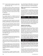
YORK recommends the field tested WEIGH-TRONIX
IMP-24, Model 2600 printer. This is a compact low cost
printer that is ideal for service work and data logging.
Paper is in the form of a compact roll and is easily handled
compared to larger printers using wider business form
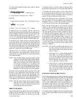
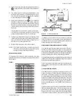
LD02099
FIG. 31
PIPING DIAGRAM
Summary of Contents for YCRJ45E00
Page 29: ...FORM 150 24 NM27 YORK INTERNATIONAL 29 CONTROL CIRCUIT With I O Expansion Board LD02106 ...
Page 30: ...30 YORK INTERNATIONAL FIG 9 SYSTEM WIRING ...
Page 31: ...FORM 150 24 NM27 YORK INTERNATIONAL 31 LD02678 ...
Page 35: ...FORM 150 24 NM27 YORK INTERNATIONAL 35 LD02679 ...
Page 36: ...36 YORK INTERNATIONAL MICROPANEL CONNECTION DIAGRAM With I O Expansion Board LD02107 ...
Page 37: ...FORM 150 24 NM27 YORK INTERNATIONAL 37 LD02108 ...


