FORM 201.25-NM1 (302)
75
YORK INTERNATIONAL
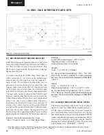
The optional Remote Reset option would be used when
reset of the chilled liquid setpoint is required and a
PWM signal (timed contact closure) cannot be supplied
by an Energy Management System. The Remote Temp.
Reset Board will convert a voltage, current, or contact
not operate. If the ambient temperature rises 1.8°F (1°C)
above signal that is available from an EMS to a PWM
signal, and every 80 seconds provide a PWM input to
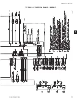
the microboard. Figure 3 shows a diagram of the field
and factory electrical connections.
If a
0 - 10VDC
signal is available, it is applied to termi-
nals A+ and A-, and
jumpers are applied to JU4 and
JU2
on the reset board. This dc signal is conditioned to
a 1 - 11 second PWM output and supplied to the PWM
input on the microboard at CTB 1 terminals 13 - 20. To
calculate the reset chilled liquid setpoint for values be-
tween 0VDC and 10VDC use the following formula:
setpoint = local chilled liquid se °reset
°reset = (dc voltage signal) x (*Max Reset Value)
10
Example:
Local Chilled Liquid Setpoint = 45°F (7.22°C)
*Max Reset Value = 20°F (11.11°C)
Input Signal = 6VDC
(English)
°reset = 6VDC x 20°F = 12°F reset
10
setpoint = 45 °F + 12 °F = 57°F
(Metric)
°reset = 6VDC x 11. 11°C = 6.67°C reset
10
setpoint = 7.22°C + 6.67°C = 13.89°C
If a
4-20mA signal is available,
it is applied to termi-
nals A+ and A- and
jumpers are applied to JU5 and
JU3
on the reset board. The mA signal is conditioned to
a 1-11 second PWM output. The PWM output is then
supplied to the PWM input on the microboard at CTB 1
terminals 13 - 20. To calculate the chilled liquid setpoint
for values between 4mA and 20 ma use the following
formula:
setpoint = local chilled liquid se °reset
°reset = (mA signal - 4) x (*Max Reset Value)
16
If the
Contact Closure input
is used. The connections
are made to terminals C and D and only
jumper JUI
must be in place
on the reset board. This input is used
when a
single
reset value is needed. When the contacts
are closed, the remote temperature reset board will con-
vert this contact closure to a PWM signal that is applied
to CTB 1 terminals 13 - 20.
To set the PWM output, the contacts must be closed on
inputs C - D, and potentiometer R11 (located on the front
edge of the PC board) is adjusted to 10VDC as mea-
sured at TP3 to terminal 10 on the circuit board. The
reset value will be the “Max EMS-PWM Remote Temp.
Reset” setpoint value programmed in the SETPOINTS
section under the Cooling Setpoints key.
NOTE: The coil of any added relay used for reset must
be suppressed to prevent possible component
damage. Use YORK PN031-00808-000
suppressor.
*Max Reset Value is the “Max EMS-PWM Remote Temp. Reset” setpoint value described in the programming section under Cooling Setpoints.
Programmable values are from 2°F to 40°F (1.11°C to 11.11°C).
A 240-24 Volt Ratio Transformer (T3)
is used to derive nominal 12 volt out-
put from the 120 volt supply.
Example:
Local Chilled Liquid Setpoint = 45° (7.22°C)
*Max Reset Value = 10°F (5.56°C)
Input Signal = 12 mA
(English)
°reset = 8mA x 10°F = 5°F reset
16
setpoint = 45°F + 5°F = 50°F
(Metric)
°reset = 8mA x 5.56°C = 2.78°C reset
16
setpoint = 7.22°C + 2.78°C = 10.0°C
7


