Safety shutdown messages
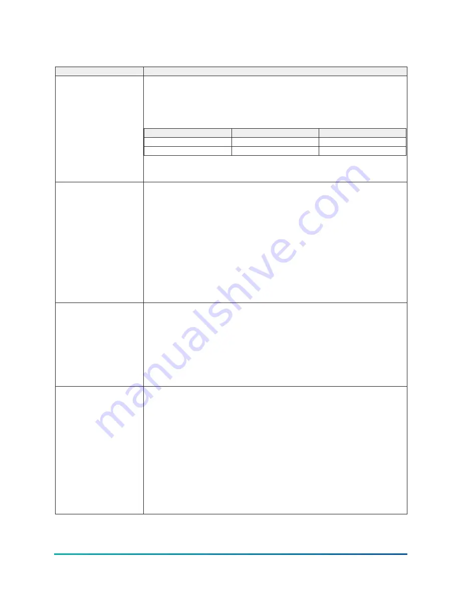
Table 143: Safety shutdown messages
Message
Description
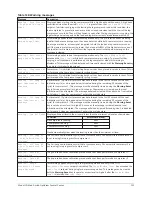
Evaporator – Low
Pressure
The evaporator pressure, as sensed by the evaporator transducer, has decreased to the
safety shutdown threshold. For water cooling applications, the safety shutdown threshold
is a fixed value for the respective refrigerant. For brine cooling applications, the safety
shutdown threshold varies according to the concentration of the brine solution. The brine
shutdown threshold is programmed at the YORK factory. It should not be changed by
anyone other than a qualified service technician.
Application
Shutdown (psig)
Restart (psig)
Water cooling R-134a
25.0
25.1
Brine cooling R-134a
6.0 to 25.0 as programmed
+0.1 > Shutdown threshold
The chiller can be started after the evaporator pressure increases to the restart threshold
and the operator presses the
Clear Faults
button.
Evaporator – Low
Pressure - Smart Freeze
Smart freeze protection is activated and has shutdown the chiller because the evaporator
temperature has been below the smart freeze threshold for greater than the allowable
number of seconds. If the evaporator refrigerant temperature sensor RT7 is enabled. This
parameter is used as the evaporator refrigerant temperature and the freeze threshold is
32.8°F. If RT7 is not enabled, the evaporator refrigerant temperature used is the evaporator
saturation temperature, derived from the evaporator pressure transducer and the freeze
threshold is 34.0°F.
The total count is incremented once for every second the evaporator refrigerant
temperature is below the freeze threshold (but is never decremented below zero). The
number of seconds it will take the chilled liquid to freeze is based on how far the evaporator
refrigerant temperature is below the freeze threshold as follows:
# seconds to freezing = (4053.7) / (freeze threshold – evap. refrigerant temp.)
Smart freeze is activated only if the feature has been enabled by a service technician and the
Leaving Chilled Liquid Temperature
setpoint is <38.0°F.
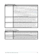
Evaporator – Transducer
Or Leaving Liquid Probe
A possible defective evaporator pressure transducer or leaving chilled liquid temperature
thermistor has been detected. The pressure and temperature that these devices are
indicating are not in the correct relationship to each other. The control center converts
the evaporator pressure to a saturated temperature value and compares this value to the
leaving chilled liquid temperature (difference = chilled liquid temp – evaporator saturated
temp). The difference should not be outside the range of –2.5°F to +25.0°F. If the transducer
and thermistor are accurate, the evaporator saturated temperature should not be > 2.5°F
warmer nor > 25.0°F colder than the leaving chilled liquid temperature. In order to initiate a
shutdown, the difference must be outside the acceptable range continuously for 10 minutes.
The chiller can be started after the operator presses the
Clear Faults
button.
EVAPORATOR – TRANSDUCER
OR TEMPERATURE SENSOR
A possible defective Evaporator pressure Transducer or Refrigerant Temperature Sensor
has been detected. The Control Center converts the evaporator pressure to a Saturated
Temperature value and compares this value to the optional Evaporator Refrigerant
Temperature Sensor. If the difference between these temperatures is greater than 3.0°F,
continuously for 1 minute, this shutdown is performed. This check is only performed under
the following conditions:
•
Chiller has been running for at least 10 minutes
•
Evaporator Refrigerant temperature (RT7) has been enabled by a Service technician
•
Not in Brine cooling mode
•
Smart Freeze is enabled
•
Evaporator Temperature Sensor (RT7) or Evaporator Saturation Temperature is
indicating a temperature of <32.0°F
The chiller can be started after the temperatures are within 3.0°F of one another and the
Operator presses the Clear Faults button.
Model YD Mod D with OptiView Control Center
140
Summary of Contents for YD Mod D
Page 2: ...2 Model YD Mod D with OptiView Control Center...
Page 8: ...Nomenclature Model YD Mod D with OptiView Control Center 8...
Page 17: ...Figure 2 Chiller operation flow chart 17 Model YD Mod D with OptiView Control Center...
Page 18: ...Figure 2 Chiller operation flow chart Model YD Mod D with OptiView Control Center 18...
Page 19: ...Figure 2 Chiller operation flow chart 19 Model YD Mod D with OptiView Control Center...
Page 20: ...Figure 2 Chiller operation flow chart Model YD Mod D with OptiView Control Center 20...
Page 21: ...Figure 2 Chiller operation flow chart 21 Model YD Mod D with OptiView Control Center...
Page 22: ...Figure 2 Chiller operation flow chart Model YD Mod D with OptiView Control Center 22...
Page 150: ...Figure 57 Sample printout status Model YD Mod D with OptiView Control Center 150...
Page 151: ...Figure 57 Sample printout status 151 Model YD Mod D with OptiView Control Center...
Page 152: ...Figure 58 Sample printout setpoints Model YD Mod D with OptiView Control Center 152...
Page 153: ...Figure 58 Sample printout setpoints 153 Model YD Mod D with OptiView Control Center...
Page 154: ...Figure 59 Sample printout schedule Model YD Mod D with OptiView Control Center 154...
Page 155: ...Figure 60 Sample printout sales order 155 Model YD Mod D with OptiView Control Center...
Page 156: ...Figure 61 Sample printout history Model YD Mod D with OptiView Control Center 156...
Page 157: ...Figure 61 Sample printout history 157 Model YD Mod D with OptiView Control Center...
Page 159: ...Figure 64 Sample printout custom screen report 159 Model YD Mod D with OptiView Control Center...

