General safety guidelines
Important:
Read before proceeding.
This equipment is a relatively complicated apparatus. During rigging, installation, operation,
maintenance, or service, individuals may be exposed to certain components or conditions including,
but not limited to: heavy objects, refrigerants, materials under pressure, rotating components, and
both high and low voltage. Each of these items has the potential, if misused or handled improperly,
to cause bodily injury or death. It is the obligation and responsibility of rigging, installation, and
operating/service personnel to identify and recognize these inherent hazards, protect themselves,
and proceed safely in completing their tasks. Failure to comply with any of these requirements could
result in serious damage to the equipment and the property in which it is situated, as well as severe
personal injury or death to themselves and people at the site.
This document is intended for use by owner-authorized rigging, installation, and operating/service
personnel. It is expected that these individuals possess independent training that will enable them
to perform their assigned tasks properly and safely. It is essential that, prior to performing any
task on this equipment, this individual shall have read and understood the on-product labels, this
document and any referenced materials. This individual shall also be familiar with and comply
with all applicable industry and governmental standards and regulations pertaining to the task in
question.
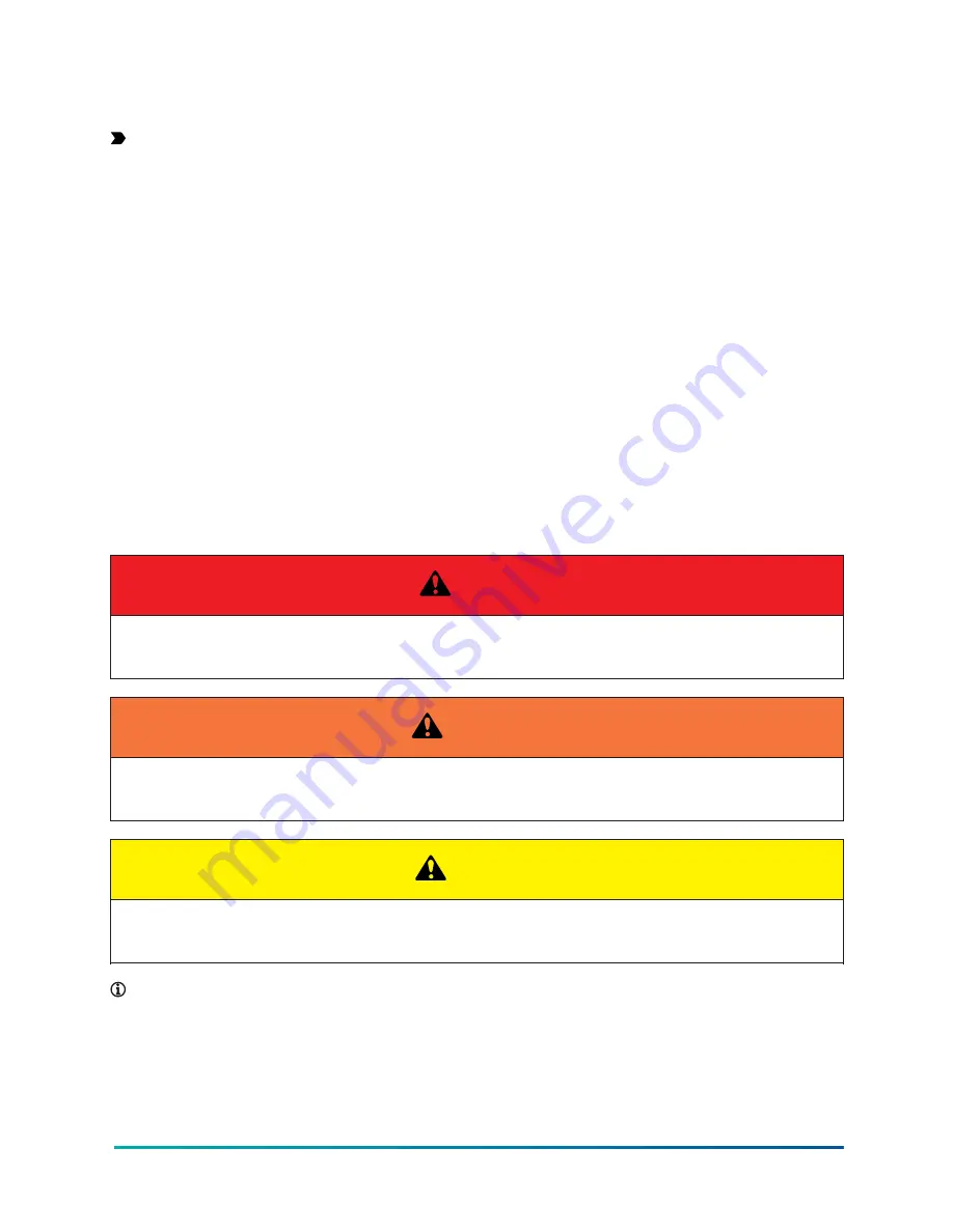
Safety symbols
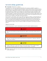
The following symbols are used in this document to alert the reader to specific situations:
DANGER
Indicates a possible hazardous situation which will result in death or serious injury if proper care is not
taken.
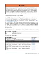
WARNING
Indicates a potentially hazardous situation which will result in possible injuries or damage to equipment
if proper care is not taken.
CAUTION
Identifies a hazard which could lead to damage to the machine, damage to other equipment and/or
environmental pollution if proper care is not taken or instructions and are not followed.
Note:
Highlights additional information useful to the technician in completing the work being
performed properly.
5
Model YD Mod D with OptiView Control Center
Summary of Contents for YD Mod D
Page 2: ...2 Model YD Mod D with OptiView Control Center...
Page 8: ...Nomenclature Model YD Mod D with OptiView Control Center 8...
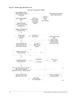
Page 17: ...Figure 2 Chiller operation flow chart 17 Model YD Mod D with OptiView Control Center...
Page 18: ...Figure 2 Chiller operation flow chart Model YD Mod D with OptiView Control Center 18...
Page 19: ...Figure 2 Chiller operation flow chart 19 Model YD Mod D with OptiView Control Center...
Page 20: ...Figure 2 Chiller operation flow chart Model YD Mod D with OptiView Control Center 20...
Page 21: ...Figure 2 Chiller operation flow chart 21 Model YD Mod D with OptiView Control Center...
Page 22: ...Figure 2 Chiller operation flow chart Model YD Mod D with OptiView Control Center 22...
Page 150: ...Figure 57 Sample printout status Model YD Mod D with OptiView Control Center 150...
Page 151: ...Figure 57 Sample printout status 151 Model YD Mod D with OptiView Control Center...
Page 152: ...Figure 58 Sample printout setpoints Model YD Mod D with OptiView Control Center 152...
Page 153: ...Figure 58 Sample printout setpoints 153 Model YD Mod D with OptiView Control Center...
Page 154: ...Figure 59 Sample printout schedule Model YD Mod D with OptiView Control Center 154...
Page 155: ...Figure 60 Sample printout sales order 155 Model YD Mod D with OptiView Control Center...
Page 156: ...Figure 61 Sample printout history Model YD Mod D with OptiView Control Center 156...
Page 157: ...Figure 61 Sample printout history 157 Model YD Mod D with OptiView Control Center...
Page 159: ...Figure 64 Sample printout custom screen report 159 Model YD Mod D with OptiView Control Center...


