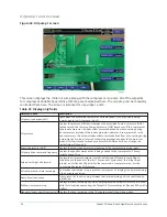
Capacity control setpoints screen
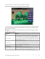
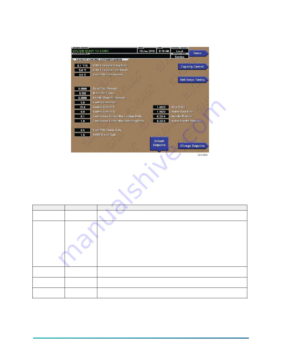
Figure 22: Capacity control setpoints screen
This screen displays the capacity control setpoints. A Service Level password is required to access
this screen.
Display only
All other parameters are view only and may be requested by Product Technical Support or Chiller
Engineering when assisting in troubleshooting.
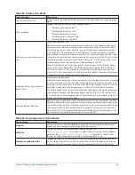
Table 51: Programmable
Button
Access level
Description
Change setpoints Service
Pressing this button highlights the first of the changeable parameters, LCHLT Setpoint
Ramp Rate.
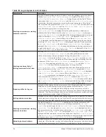
LCHLT setpoint
ramp rate
Service
When the chiller is not running, the Active Setpoint is set to Entering Chilled Liquid
Temperature minus a programmable offset (default 5°F), but not adjusted to less
than the programmed LCHLT setpoint. When the compressor motor starts, the Active
LCHLT Setpoint is ramped from this value to the programmed LCHLT Setpoint at
the programmable LCHLT Setpoint Ramp Rate (default 0.1°F/second). This keeps
the chiller from undershooting setpoint excessively during pulldown. Any time the
programmed setpoint is changed during operation, the active setpoint is ramped to
the new value at this rate (adjustable 0.1°F/second to 2.0°F/second, default 0.1°F/
second).
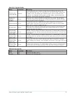
LCHLT setpoint
start offset
Service
The LCHLT setpoint offset above the Active setpoint. (Adjustable 0.0°F to 10.0°F,
Default 5.0°F).
Lead PRV start
position
Service
The desired start position of the Lead compressor PRV. (Adjustable 0% to 100%,
Default 0%).
Gear ratio
override
Service
Allows the technician to add a buffer above the operating surge plane by adjusting
this parameter. (Adjustable 0.0000 to 7.0000, Default 0.0000).
65
Model YD Mod D with OptiView Control Center
Summary of Contents for YD Mod D
Page 2: ...2 Model YD Mod D with OptiView Control Center...
Page 8: ...Nomenclature Model YD Mod D with OptiView Control Center 8...
Page 17: ...Figure 2 Chiller operation flow chart 17 Model YD Mod D with OptiView Control Center...
Page 18: ...Figure 2 Chiller operation flow chart Model YD Mod D with OptiView Control Center 18...
Page 19: ...Figure 2 Chiller operation flow chart 19 Model YD Mod D with OptiView Control Center...
Page 20: ...Figure 2 Chiller operation flow chart Model YD Mod D with OptiView Control Center 20...
Page 21: ...Figure 2 Chiller operation flow chart 21 Model YD Mod D with OptiView Control Center...
Page 22: ...Figure 2 Chiller operation flow chart Model YD Mod D with OptiView Control Center 22...
Page 150: ...Figure 57 Sample printout status Model YD Mod D with OptiView Control Center 150...
Page 151: ...Figure 57 Sample printout status 151 Model YD Mod D with OptiView Control Center...
Page 152: ...Figure 58 Sample printout setpoints Model YD Mod D with OptiView Control Center 152...
Page 153: ...Figure 58 Sample printout setpoints 153 Model YD Mod D with OptiView Control Center...
Page 154: ...Figure 59 Sample printout schedule Model YD Mod D with OptiView Control Center 154...
Page 155: ...Figure 60 Sample printout sales order 155 Model YD Mod D with OptiView Control Center...
Page 156: ...Figure 61 Sample printout history Model YD Mod D with OptiView Control Center 156...
Page 157: ...Figure 61 Sample printout history 157 Model YD Mod D with OptiView Control Center...
Page 159: ...Figure 64 Sample printout custom screen report 159 Model YD Mod D with OptiView Control Center...

