Description of system and fundamentals of
operation
System operation description
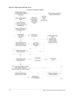
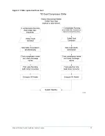
The following is a high-level description of the chiller control. It describes the overall operation.
Control Center components, chiller components and programmable setpoints are referenced. See
Figure 2 to view the chiller operation flowchart.
The YD dual compressor chiller consists of one evaporator, one condenser, two oil pumps and
two compressors. Other than capacity control, the basic operation is similar to a standard YK
Centrifugal Chiller.
The use of two compressors requires valves on the discharge line of each compressor. When a
compressor is shut down, its discharge valve is closed to prevent compressor backspin due to a gas
flow from the running compressor. An end switch at both the closed and open positions provides
indication of full open and full closed positions. The operator can manually control the valves.
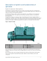
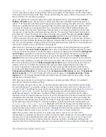
Figure 1: Model YD chiller
Callout Description
Callout Description
1
Compressor 1
2
Unit-mounted starter 1
3
Compressor 2
4
Unit-mounted starter 2
5
Evaporator
6
Control panel
Each compressor pre-rotation vane assembly is equipped with a potentiometer to provide vane
position. A calibration procedure ensures displayed position accuracy. The vanes can be manually
controlled.
Each compressor also has a discharge temperature thermistor and high-pressure safety device.
There are two Liquid Line Solenoid Valves and two Oil Return Solenoid Valves, one for each
compressor.
9
Model YD Mod D with OptiView Control Center
Summary of Contents for YD Mod D
Page 2: ...2 Model YD Mod D with OptiView Control Center...
Page 8: ...Nomenclature Model YD Mod D with OptiView Control Center 8...
Page 17: ...Figure 2 Chiller operation flow chart 17 Model YD Mod D with OptiView Control Center...
Page 18: ...Figure 2 Chiller operation flow chart Model YD Mod D with OptiView Control Center 18...
Page 19: ...Figure 2 Chiller operation flow chart 19 Model YD Mod D with OptiView Control Center...
Page 20: ...Figure 2 Chiller operation flow chart Model YD Mod D with OptiView Control Center 20...
Page 21: ...Figure 2 Chiller operation flow chart 21 Model YD Mod D with OptiView Control Center...
Page 22: ...Figure 2 Chiller operation flow chart Model YD Mod D with OptiView Control Center 22...
Page 150: ...Figure 57 Sample printout status Model YD Mod D with OptiView Control Center 150...
Page 151: ...Figure 57 Sample printout status 151 Model YD Mod D with OptiView Control Center...
Page 152: ...Figure 58 Sample printout setpoints Model YD Mod D with OptiView Control Center 152...
Page 153: ...Figure 58 Sample printout setpoints 153 Model YD Mod D with OptiView Control Center...
Page 154: ...Figure 59 Sample printout schedule Model YD Mod D with OptiView Control Center 154...
Page 155: ...Figure 60 Sample printout sales order 155 Model YD Mod D with OptiView Control Center...
Page 156: ...Figure 61 Sample printout history Model YD Mod D with OptiView Control Center 156...
Page 157: ...Figure 61 Sample printout history 157 Model YD Mod D with OptiView Control Center...
Page 159: ...Figure 64 Sample printout custom screen report 159 Model YD Mod D with OptiView Control Center...


