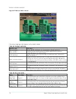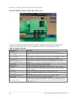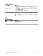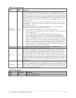
Electro-mechanical starter screen
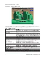
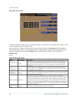
Figure 34: Electro-mechanical starter screen
This screen displays the information about both compressor motors operation when the chiller is
using electro-mechanical starters. Also the
Current Limit
setpoints are maintained here.
Table 80: Display only fields
Field/LED name
Description
Lead compressor
Identifies the compressor that has been selected as the lead compressor.
Chiller current limit setpoint
Displays the Chiller Current Limit Setpoint. The Chiller Current Limit Setpoint could
come from 0-20 mA, 4-20 mA, 0-10 VDC or 2-10 VDC in Analog Remote mode, PWM in
Digital Remote mode, SC-EQ communications interface in ISN (BAS) mode, or the Local
Chiller Current Limit Setpoint that is entered at the Keypad. The Chiller Current is the
total motor current being conducted by the chiller. If only one compressor motor is
running, that is the Chiller Current. If both compressor motors are running, the Chiller
Current is the total of both motors, with the Pre-rotation Vanes operated to achieve
equal current to both motors.
The Chiller Full Load Amps (FLA) is the total of compressor #1 motor and compressor
#2 motor FLA ratings, with each motor having an equal FLA rating. For example, if the
Chiller FLA is 1600 A, the FLA of each motor is 800 A. The Chiller Current Limit Setpoint
is expressed as a percentage (30% to 100%) of Chiller FLA. In this example, the chiller
FLA is 1600 A. If the Chiller Current Limit Setpoint is set at 70%, the Chiller Current is
limited to 1120 A. If only one motor is running, the Motor Current Limit (see
and 2: Motor current limit setpoint
) for that motor would be set to 100% and it would
be allowed to operate at its maximum of 800 A, However, if both motors are running,
each would be limited to 560 A per motor, producing a Chiller Current of 1120 A.
This setpoint is in effect after the Lead Compressor Pulldown Time setpoint (see
below) has elapsed and for the remainder of system run.
Motor 1 and 2: Motor run (LED)
Lights when compressor #1 motor is being commanded to run. Otherwise, off.
Motor 1 and 2: % Full Load Amps
Displays the motor current of compressor #1 motor as a percentage of the Full Load
Amps of that motor.
Model YD Mod D with OptiView Control Center
90
Summary of Contents for YD Mod D
Page 2: ...2 Model YD Mod D with OptiView Control Center...
Page 8: ...Nomenclature Model YD Mod D with OptiView Control Center 8...
Page 17: ...Figure 2 Chiller operation flow chart 17 Model YD Mod D with OptiView Control Center...
Page 18: ...Figure 2 Chiller operation flow chart Model YD Mod D with OptiView Control Center 18...
Page 19: ...Figure 2 Chiller operation flow chart 19 Model YD Mod D with OptiView Control Center...
Page 20: ...Figure 2 Chiller operation flow chart Model YD Mod D with OptiView Control Center 20...
Page 21: ...Figure 2 Chiller operation flow chart 21 Model YD Mod D with OptiView Control Center...
Page 22: ...Figure 2 Chiller operation flow chart Model YD Mod D with OptiView Control Center 22...
Page 150: ...Figure 57 Sample printout status Model YD Mod D with OptiView Control Center 150...
Page 151: ...Figure 57 Sample printout status 151 Model YD Mod D with OptiView Control Center...
Page 152: ...Figure 58 Sample printout setpoints Model YD Mod D with OptiView Control Center 152...
Page 153: ...Figure 58 Sample printout setpoints 153 Model YD Mod D with OptiView Control Center...
Page 154: ...Figure 59 Sample printout schedule Model YD Mod D with OptiView Control Center 154...
Page 155: ...Figure 60 Sample printout sales order 155 Model YD Mod D with OptiView Control Center...
Page 156: ...Figure 61 Sample printout history Model YD Mod D with OptiView Control Center 156...
Page 157: ...Figure 61 Sample printout history 157 Model YD Mod D with OptiView Control Center...
Page 159: ...Figure 64 Sample printout custom screen report 159 Model YD Mod D with OptiView Control Center...

