Display messages
The status bar of the display contains a status line and, beneath it a details line. The status line
contains a message describing the operating state of the chiller; whether it is stopped, running,
starting or shutting down. The details line displays Warning, Cycling, Safety, Start Inhibit and other
messages that provide further details of the status bar messages. The status messages listed below
are displayed on the status line. All other messages are displayed on the details line.
To aid in the meaning of the message, messages are displayed in different colors as follows:
•
Normal operation - Green
•
Warning - Yellow
•
Cycling shutdown - Orange
•
Safety shutdown - Red
Status messages
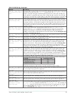
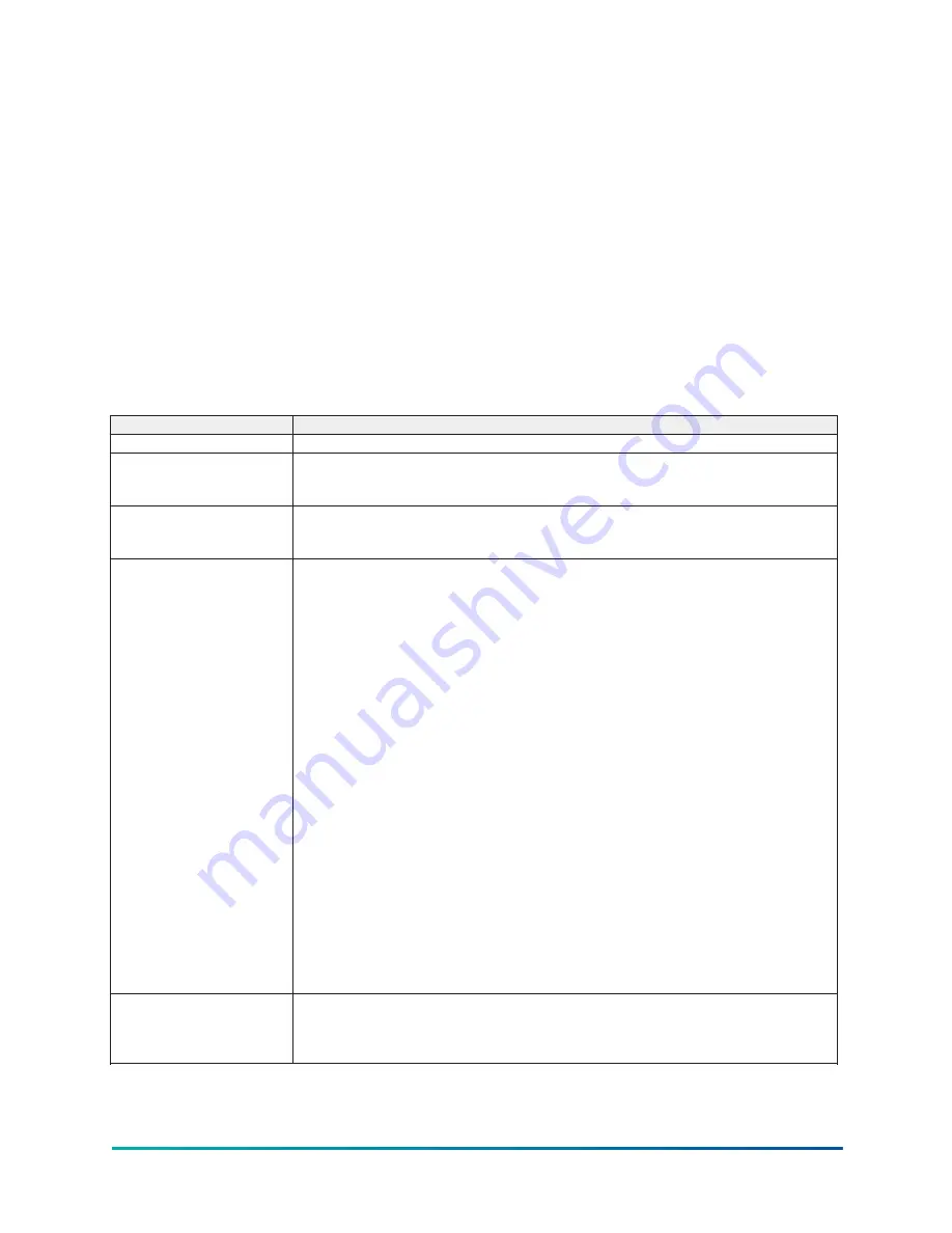
Table 137: Status messages
Message
Description
System Ready To Start
The chiller is shut down but will start upon receipt of a Local or Remote start signal.
Cycling Shutdown – Auto
Restart
The chiller is shut down on a CYCLING shutdown. The cause of the shutdown is still in effect
and is displayed on the Details line of the Status Bar. The chiller will automatically restart
when the CYCLING condition clears.
Safety Shutdown –
Manual Restart
The chiller is shut down on a
SAFETY
shutdown. The cause of the shutdown is still in effect
and is displayed on the Details line of the Status Bar. The chiller can be started after the
Safety condition clears and the Operator presses the Clear Fault button on the Home screen.
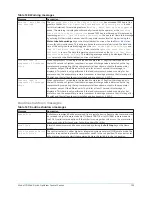
System Unloading Before
Shutdown
Displayed while the Pre-rotation Vanes and Discharge Valves are closing during a soft
shutdown of the entire chiller. A soft shutdown is performed on the running compressors for
the following shutdowns:
•
Leaving Chilled Liquid Temperature – Low Temperature
•
Remote Stop (ISN, Analog Remote or Digital Remote)
•
Control Panel-Schedule
•
Multiunit Cycling-Contacts Open
•
System Cycling #1-Contacts Open
•
System Cycling #1-Contacts Open
•
Discharge #1-Valve Not Closed
•
Discharge #2-Valve Not Closed
•
Operator initiated at Keypad
When a soft shutdown is initiated on the entire chiller, a close command is applied to the
pre-rotation vanes. If both compressors are running, a vanes close command is applied
simultaneously to both compressors. When the vane motor switch for each compressor
closes, indicating its vanes have closed (or 3.5 minutes have elapsed, whichever occurs
first), a close command is applied to the discharge valve for the respective compressor.
When the discharge valve limit switch closes, indicating the valve has closed (or 40 seconds
have elapsed, whichever occurs first), the chiller enters coastdown. If both compressors are
running, the chiller will enter coastdown only after both discharge valves have closed or
timed out.
While the vanes are closing during a soft shutdown, if a Local stop or any faults listed above
occur, the soft shutdown is terminated and the chiller immediately enters coastdown.
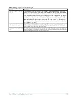
System Prelube
A chiller start has been initiated and the pre-start lubrication is being performed on the Lead
compressor. The Prelube duration is either 50 seconds or 180 seconds, as configured with a
Microboard Program Switch. The Pre-lube duration must never be changed by anyone other
than a qualified Service Technician. The standard Prelube duration is 50 seconds.
129
Model YD Mod D with OptiView Control Center
Summary of Contents for YD Mod D
Page 2: ...2 Model YD Mod D with OptiView Control Center...
Page 8: ...Nomenclature Model YD Mod D with OptiView Control Center 8...
Page 17: ...Figure 2 Chiller operation flow chart 17 Model YD Mod D with OptiView Control Center...
Page 18: ...Figure 2 Chiller operation flow chart Model YD Mod D with OptiView Control Center 18...
Page 19: ...Figure 2 Chiller operation flow chart 19 Model YD Mod D with OptiView Control Center...
Page 20: ...Figure 2 Chiller operation flow chart Model YD Mod D with OptiView Control Center 20...
Page 21: ...Figure 2 Chiller operation flow chart 21 Model YD Mod D with OptiView Control Center...
Page 22: ...Figure 2 Chiller operation flow chart Model YD Mod D with OptiView Control Center 22...
Page 150: ...Figure 57 Sample printout status Model YD Mod D with OptiView Control Center 150...
Page 151: ...Figure 57 Sample printout status 151 Model YD Mod D with OptiView Control Center...
Page 152: ...Figure 58 Sample printout setpoints Model YD Mod D with OptiView Control Center 152...
Page 153: ...Figure 58 Sample printout setpoints 153 Model YD Mod D with OptiView Control Center...
Page 154: ...Figure 59 Sample printout schedule Model YD Mod D with OptiView Control Center 154...
Page 155: ...Figure 60 Sample printout sales order 155 Model YD Mod D with OptiView Control Center...
Page 156: ...Figure 61 Sample printout history Model YD Mod D with OptiView Control Center 156...
Page 157: ...Figure 61 Sample printout history 157 Model YD Mod D with OptiView Control Center...
Page 159: ...Figure 64 Sample printout custom screen report 159 Model YD Mod D with OptiView Control Center...


