JOHNSON CONTROLS
10
FORM 160.69-O1
ISSUE DATE: 9/30/2012
SECTION 1 – DESCRIPTION OF SYSTEM AND FUNDAMENTALS OF OPERATION
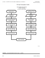
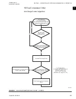
The Chiller Current Limit setpoints are used to specify
the motor current limit for the chiller as a whole. There
are two setpoints: the Chiller Pulldown Demand Limit
setpoint (in effect during the Chiller Pulldown Period)
and the Chiller Current Limit setpoint (in effect after
the Chiller Pulldown Period). These setpoints (pro-
grammable over the range of 30% to 100% FLA) are
applied to the Chiller Full Load Amp (FLA) rating,
which is the combined total of the full load amp ratings
of both motors. Each motor provides one-half of the
Chiller Full Load Amps. For example, if the Chiller
Full Load Amps is 1600 amps, the Full Load Amps of
each motor is 800 amps. If the Chiller Current Limit
setpoint is 70%, the total chiller motor current is lim-
ited to 1120 amps. If both motors are running, each
would be limited to 560 amps, providing a chiller total
of 1120 amps. If only one motor is running, it is al-
lowed to operate at twice the Chiller Current Limit, up
to 100%. In this example, with the total chiller current
limited to 1120 amps, one running motor would be al-
lowed to operate at its 100% FLA rating of 800 amps.
COMPRESSOR STARTING
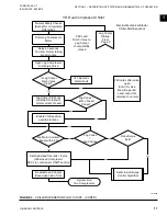
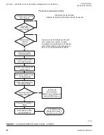
Both compressors are not started at the same time. The
“Lead” compressor is started first. If it does not meet
the load demand during the Chiller Pulldown Period
and later during the Chiller Steady State Period, the
Lag compressor is brought on line.
There are three features that can be used to prevent
the second compressor from being brought on line.
The COMPRESSOR LOCKOUT setpoint can be used
to lockout either compressor. The compressor des-
ignated for lockout will not be permitted to run. The
COMRESSOR MODE Setpoint (Software version
C.OPT.11.03.01.004(or later)) selects either Normal
or Single Compressor mode of operation. In Normal
Mode, the Lag compressor is brought on line, if neces-
sary, to meet the load requirement as described below.
In Single Mode, the Lag compressor will not be brought
on line, regardless of the load requirement. The LEAD
COMPRESSOR PULLDOWN DEMAND LIMIT
Setpoint (Software version C.OPT.11.03.01.004 or
later), can be used to load the chiller slowly. It pre-
vents the Lag compressor from coming on line for a
specified period of time while limiting the motor cur-
rent of the Lead compressor to a specified value during
that time period. These features are detailed separately
below.
If equipped with the compressor Variable Geometry
Diffuser (VGD), the chiller is started with the VGD in
the fully open position.
Upon receipt of a chiller start signal, the “Lead” com-
pressor is selected. The compressor with the least
amount of run time that is ready to run is selected as
the “Lead” compressor (unless Locked-out) . The Lead
compressor enters the Prelube period (Prelube duration
determined by Program Switch SW1-3) and the Lead
compressor Discharge Valve is opened. All normal
Prelube functions are performed. If the Lead compres-
sor Discharge Valve does not fully open (as indicated
by the Discharge Valve Limit Switch) within 40 sec-
onds, a Safety shutdown is performed and “Discharge
#X – Valve Not Opened” is displayed. Upon entering
Pre-lube, the refrigerant level control raise (close) out-
put to the Variable Orifice is energized for the duration
of the Valve Preset Time Setpoint (0-100 seconds). Af-
ter this pre-positioning, the valve is held in this posi-
tion for the first 3 minutes of compressor operation.
Upon completion of the Prelube period, the Lead com-
pressor motor is started and the
Chiller Pulldown Pe-
riod
begins. This period is in effect until the Leaving
Chilled Liquid Temperature is within 2 ºF of the Leav-
ing Chilled Liquid Temperature Setpoint. During this
period, the Pre-rotation Vanes are modulated to achieve
the Leaving Chilled Liquid Temperature Setpoint. Af-
ter the first 3 minutes of compressor operation and for
the remainder of the Chiller Pulldown Period, the rate
of change of the Leaving Chilled Liquid Temperature
is monitored to determine if the Lead compressor is
meeting the load demand requirements. The Leaving
Chilled Liquid temperature is sampled at one-minute
intervals. If the rate of change of the Liquid Tempera-
ture (
Delta T Rate
) is less than the programmed
Mini-
mum Rate Setpoint
(0.5 ºF/minute to 2.0 ºF/minute;
default 1.0 ºF/minute) for a period equal to the
Mini-
mum Rate Time Setpoint
(1 to 20 minutes; default 5
minutes) and the Pulldown Demand Limit Setpoint is
above 50%, the Lag compressor is brought on line. If
a Lead Compressor Pulldown Demand Limit Setpoint
has been entered (software version C.OPT.11.03.01.004
(and later)), the Lag compressor will not be brought on
line until this time has elapsed.
When the first 3 minutes of compressor operation has
elapsed, if the refrigerant level is greater than or equal
to the
Level Control Setpoint
, the level is controlled
to the Level Setpoint. However, if the level is less than
the Level Control setpoint, a linearly increasing ramp
called the
Refrigerant Level Target
is applied to the


