JOHNSON CONTROLS
79
SECTION 2 – OPTIVIEW CONTROL CENTER
FORM 160.69-O1
ISSUE DATE: 9/30/2012
2
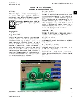
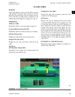
ELECTRO-MECHANICAL STARTER SCREEN
Overview
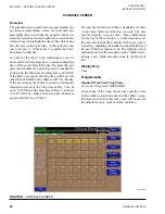
This screen displays all information pertaining to both
compressor motors operation. Also the Current Limit
setpoints are maintained here.
Display Only
Lead Compressor
Identifies the compressor that has been selected as the
lead compressor.
Chiller Current Limit Setpoint
Displays the Chiller Current Limit Setpoint. The Chill-
er Current Limit Setpoint could come from 0-20mA,
4-20mA, 0-10Vdc or 2-10Vdc in Analog Remote
mode, PWM in Digital Remote mode, Microgate-
way interface in ISN mode or the Local Chiller Cur-
rent Limit Setpoint that is entered at the Keypad. The
Chiller Current is the total motor current being con-
ducted by the chiller. If only one compressor motor is
running, that is the Chiller Current. If both compressor
motors are running, the Chiller Current is the total of
both motors, with the Pre-rotation Vanes operated to
achieve equal current to both motors. The Chiller Full
Load Amps (FLA) is the total of compressor #1 mo-
tor and compressor #2 motor FLA ratings, with each
motor having an equal FLA rating. For example, if
the Chiller FLA is 1600 amps, the FLA of each mo-
tor is 800 amps. The Chiller Current Limit Setpoint is
expressed as a percentage (30% to 100%) of Chiller
FLA. In this example, the chiller FLA is 1600 amps.
If the Chiller Current Limit Setpoint is set at 70%, the
Chiller Current is limited to 1120 amps. If only one
motor is running, the Motor Current Limit (see Motor
Current Limit Setpoint above) for that motor would be
set to 100% and it would be allowed to operate at its
maximum of 800 amps, However, if both motors are
running, each would be limited to 560 amps per motor,
producing a Chiller Current of 1120 amps.
If equipped with software version C.OPT.11.02B.xxx
(and earlier), this setpoint comes into effect during the
Chiller Steady State Period (this period is in effect after
the Leaving Chilled Liquid Temperature is within 2ºF
of the Leaving Chilled Liquid Temperature Setpoint
(Chiller Pulldown Period no longer in effect)) and re-
mains in effect for the remainder of System Run. If
equipped with software version C.OPT.11.03.01.004
(and later), this setpoint is in effect after the Lead
Compressor Pulldown Time setpoint (see below) has
elapsed and for the remainder of system run.
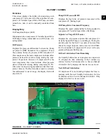
FIGURE 27 -
ELECTRO-MECHANICAL STARTER SCREEN
LD08624


