FORM 150.75-NM2
17
YORK INTERNATIONAL
LD01922
TYPE
MAX. LOAD
SPRING
DEFL
& SIZE
LBS. (KG)
COLOR
IN. (MM)
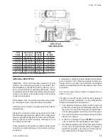
CP-2-25
900 (408.2)
RED
1.22 (30.9)
CP-2-26
1200 (544.3)
PURPLE
1.17 (29.7)
CP-2-27
1500 (680.4)
ORANGE
1.06 (26.9)
CP-2-28
1800 (816.4)
GREEN
1.02 (25.9)
CP-2-31
2200 (997.9)
GRAY
0.83 (21.0)
CP-2-32
2600 (1179.3)
WHITE
0.74 (18.7)
CP-2-35
1
3000 (1360.8)
GOLD
0.70 (17.7)
NOTE: 1. Free height 1/2" (12.7) higher than shown.
GENERAL LIQUID PIPING
GENERAL When liquid has been located in its final
position, the unit liquid piping may be connected. Nor-
mal installation precautions should be observed in or-
der to receive maximum operating efficiencies. Piping
should be kept free of all foreign matter. All liquid cooler
piping must comply in all respects with local plumbing
codes and ordinances.
Since elbows, tees, and valves decrease pump capac-
ity, all piping should be kept as simple as possible.
Hand stop valve should be installed in all lines to facili-
tate servicing.
Piping to the inlet and outlet connections of the chiller
should include high-pressure rubber hose or piping loops
to insure against transimission of water pump vibration.
This is optional and the necessary components must
be obtained in the field.
Drain connections should be provided at all low points
to permite complete drainage of liquid cooler and pip-
ing system.
A small valve or valves should be installed at the highest
point or points in the chilled liquid piping to allow any
trapped air to be purged. Vent and drain connections
should be extended beyond the insulation to make them
accessible.
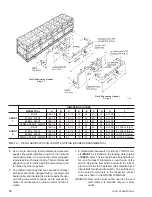
Two typcial water piping header arrangements are
shown in Fig. 13.
The piping to and from each cooler must be designed
to suit the individual installation. It is important that the
following considerations be observed:
1. The chilled liquid piping system should be laid out
so that the circulating pump discharges directly into
the cooler. The suction for this pump should be taken
from the piping system return line and not the cooler.
2. The inlet and outlet cooler liquid connection sizes
are given on page 9.
3. A strainer, preferably 40 mesh,
MUST
be installed
in the cooler inlet line just ahead of each cooler.
4. All chilled liquid piping should be thoroughly flushed
to free it from foreign material before the system is
placed into operation. Use care not to flush any for-
eign material into or through the cooler.


