YORK INTERNATIONAL
20
REMOVING THE IMPELLER (HF COMPRESSORS)
1. Before removing the impeller, measure and record
the following. (See Fig. 27) Position compressor so
that it is sitting on the correct horizontal plane to
assure correct readings
a. Impeller rim Runout (Design 0.003" Maximum)
b. Impeller eye Runout (Design 0.002" Maximum)
c. High Speed Axial thrust (Design 0.009"
to 0.020")
d. Low Speed Axial Thrust (Design 0.011"
to 0.019")
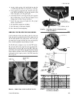
2. Install the gear locking tool on the low-speed shaft.
(See Fig. 52)
3. Remove the cap screw from the impeller.
Install Puller Plate and Puller Tool, found in the tool
kit, onto the impeller. Apply a wrench to the puller
to remove the impeller clamping color.
Considerable torque will have to be
applied to the wrench in order to re-
move the impeller-clamping collar.
REMOVING BALANCE PISTON SEAL AND DIFFUSER
PLATE
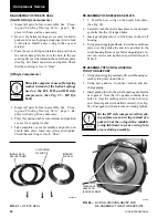
1. Remove the (3) socket head cap screws (shoulder
bolts) that fasten the balance piston retainer and
balance piston seal the to diffuser plate. (See Fig.
32 and 33)
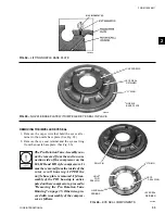
2. Remove (2) of the (6) cap screws that secure the
diffuser plate to the bearing housing. Insert guide
pins where cap screws were removed. Loosen the
(4) remaining cap screws. (See Fig. 34) Insert jack-
ing screws into holes to loosen diffuser plate from
bearing housing.
3. Insert eyebolts from tool kit into jacking holes and
use proper rigging methods to lift diffuser plate from
compressor. Also remove o-ring from back of dif-
fuser plate.
Original design balance piston seal on
HA, HB, and HD style compressors
were equipped with (8) coil springs.
Current design on these compressors
use (16) coil springs. On the HF style
compressor the balance piston seal
uses a flat spring washer in place of
the coil springs. (See Fig. 35 - HF style
Balance Piston Seal Assembly)
2. Install the gear locking tool on the low-speed shaft.
(See Fig. 52)
3. Remove the cap screw and O-ring from the impel-
ler-clamping collar.
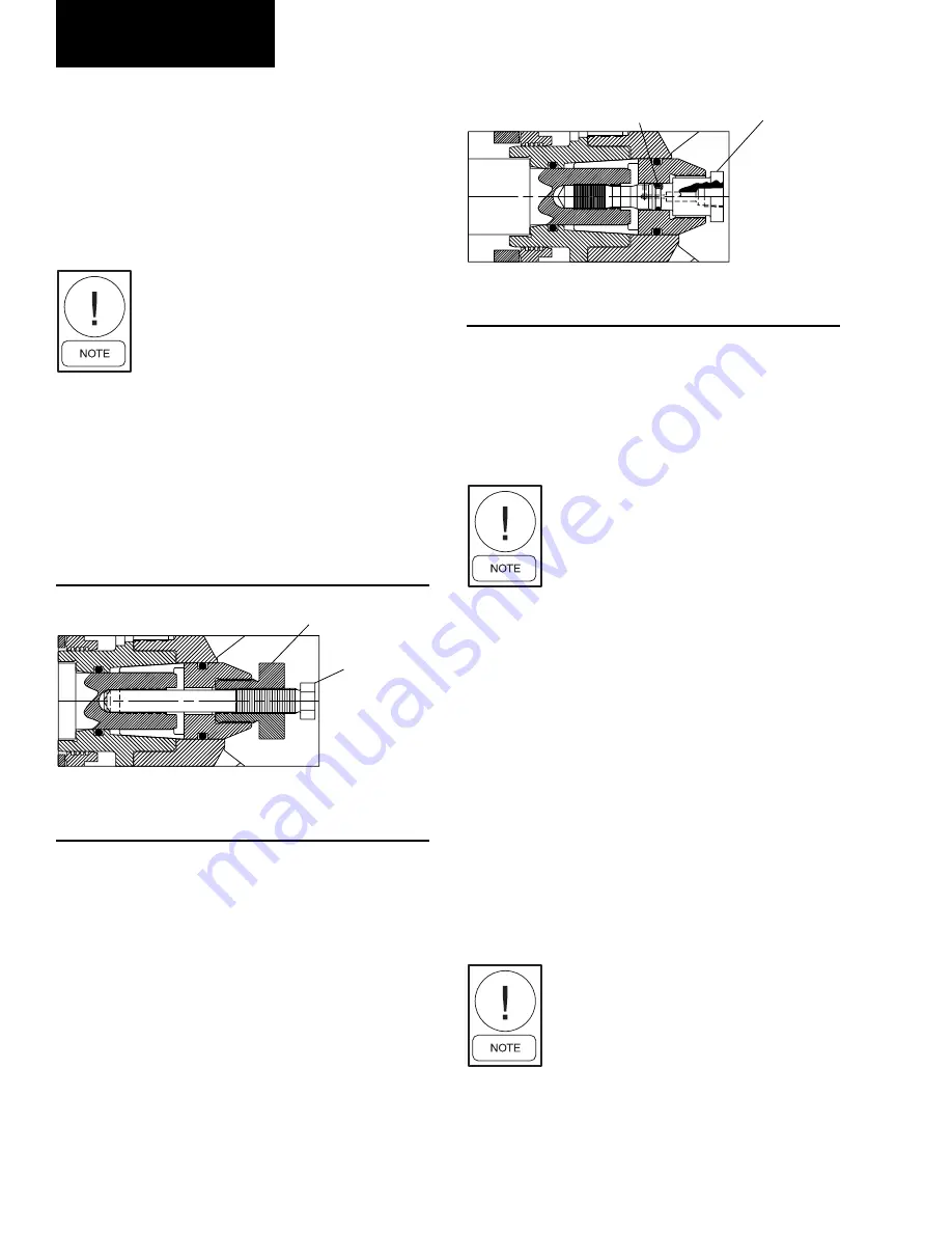
4. Mechanical Method – Install the adaptor and puller
tool, found in the tool kit, as shown in Fig. 30. Apply
a wrench to the puller tools to remove the impeller
clamping collar.
Considerable torque will have to be
applied to the wrench in order to re-
move the impeller-clamping collar.
4a. Hydraulic Method – Install the hydraulic removal
tool, found in the tool kit, as shown in Fig. 31. Con-
nect a source of hydraulic pressure (5000 PSI mini-
mum) to the head of the removal tool (1/8" NPT).
Carefully and gradually apply hydraulic pressure until
the clamping collar is loosened.
5. Pull the impeller from the high speed shaft. Use
care when removing the impeller so that the bal-
ance piston seal is not damaged.
"O" RING
HYDRAULIC
TOOL
FIG. 31 –
REMOVING THE IMPELLER
(IMPELLER SIZES 36 & 41)
LD04761
ADAPTER
PULLER TOOL
FIG. 30 –
REMOVING THE IMPELLER
(IMPELLER SIZES 36 & 41)
LD04760
Compressor Service


