APPENDIX 1 - CHECKLIST
FORM 155.32-ICOM2.EN.UL
ISSUE DATE:1/10/2018
176
JOHNSON CONTROLS
JOHNSON CONTROLS
4
FORM 155.32-CL1
ISSUE DATE: 03/31/2017
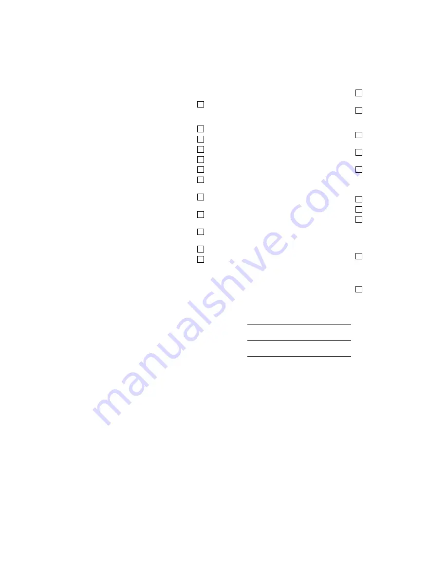
START UP
A. Operation Check
1. Press the Control Valve Mode
Auto
button. ............
2. Check that the capacity control valve works
automatically according to the chilled water outlet
temperature. .............................................................
3. Press the
STOP
button on the Control Panel ..........
4. Check that the dilution process completes. .............
5. Press the
OPER.
button on the Control Panel. ........
6. Operate the chiller-heater for 3 hours or longer. ......
7. Close the refrigerant manual blow valve. .................
8. Operate the chiller-heater for an additional hour or
longer. ......................................................................
9. Check that the cooling water temperature is con-
trolled within the acceptable range. .........................
10. Check that the specific gravity of the refrigerant is
within the acceptable range. ....................................
11. Check that the chilled water outlet temperature is
lower than the chilled water inlet temperature. ........
12. Record the running data on the data sheets. ...........
B. Purge Amount Check
1. Verify that the purge amount from the absorber is
within acceptable range ...........................................
2. Close the spindle valve to facilitate purging from
the absorber. ............................................................
3. Continuously purge from the purge tank until the
exhausted gas amount reduces and becomes
stable. ......................................................................
4. Operate the chiller for about 1 hour without operat-
ing the vacuum pump. ..............................................
5. Verify that the amount of purge from the purge
tank is within the acceptable range. .........................
C. Purge System Check
1. Press the Purge Mode
Auto
button .........................
2. Change the lubricant oil of the vacuum pump ..........
3. Open the valve of the ballast valve part-way. ..........
D. Remote Operation Check
&RQ¿UPWKDWWKHFKLOOHUKHDWHUVWDUWVDQGVWRSVSURS
-
erly using the remote signal. .........................................
E. Operation Instruction
Review the operation and maintenance instructions
with the customer. .........................................................
a. Customer Names:
1.
2.
3.
Customer Signature:
_______________________________________
Form Completed by:
_______________________________________
_______________________________________
Title:
____________ / ____________ /
___________
Month
Day
Year
Date:


