FORM 155.32-ICOM2.EN.UL
SECTION 4 - TECHNICAL DATA
ISSUE DATE:1/10/2018
JOHNSON CONTROLS
81
4-wire Type Cable Diagrams
The following are sample cable diagrams for 4-wire type connections that use a GP4000
series (COM2).
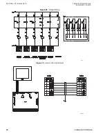
Figure 38 -
4-wire 1:1 Connection With User-Created Cable
Figure 39 -
4-wire N:1 Connection With User-Created Cable
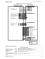
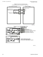
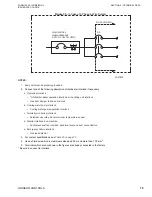
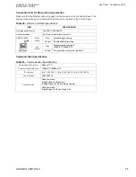
The following table contains information about the communication specifications needed
for the Modbus RTU. For information about the Read Command , see
or for information about the Write Command, see
Table 28 -
Communication Specifications
COMMUNICATION
PROTOCOL
MODBUS/RTU
Communication
Path Type
RS422/RS485 Data Length: 8 Bit Stop Bit: 1 Bit Parity: EVEN Speed:
9600 bps
Connector
D-Sub 9pin
Function Code
Read Coil Status:01 Read Holding Register:03
Device
Digital Signal: Coil Analog Signal: Holding Register
Slave Equipment
Address
1
SDA
SDB
RDA
RDB
SG
2
3
7
5
4
SG
1
RDB
SDA
SDB
RDA
9
6
CSA
ERB
CSB
ERA
8
100
Ω
(1/2W)
100
Ω
(1/2W)
Display
Shield
(Slave)
D-sub 9 pin (socket)
Signal name
External Device
(Master)
Your own cable
Pin
Signal name
Termination
resistance
Termination
resistance
Shell
FG
LD20946
LD20947
2
3
7
5
4
SG
1
RDB
SDA
SDB
RDA
9
6
CSA
ERB
CSB
ERA
8
SDA
SDB
RDA
RDB
SG
FG
2
3
7
5
4
SG
1
RDB
SDA
SDB
RDA
9
6
CSA
ERB
CSB
ERA
8
FG
FG
Termination
Resistance
100Ω (1/2W)
External Device
(Master)
Shield
(Slave)
D-sub 9 Pin
(socket)
Shield
(Slave)
D-sub 9 Pin
(socket)
Termination
Resistance
100Ω (1/2W)
Signal Name
Pin
Shell
Shell
Signal Name
Signal Name
Your own cable
Pin
Display

