SECTION 8 – TROUBLESHOOTING
FORM 155.32-ICOM2.EN.UL
ISSUE DATE:1/10/2018
168
JOHNSON CONTROLS
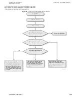
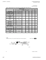
Figure 77 -
Troubleshooting Sequence Flow Chart
LD22955
Emergency stop
Audible alarm
(buzzer) “ON”
Dilution operation time
calculation
Chilled water
and/or refrigerant
temp. low cut-
Dilution Finish
• Operation interlock
• Cooling water pump interlock
• Constantly monitoring interlock
• Combustion monitoring interlock
• Low cooling water inlet temperature
• HG high temperature / high pressure
• High cut
• High exhaust gas temperature
• Flame failure
• Fuel line abnormal
• HG low liquid level
• Burner fan / Oil pump abnormal
• Control sensor abnormal
• CPU abnormal
Failure indicator
light “ON”
1
1
Yes
Yes
No
No
No
Yes
Reset operation
(buzzer “OFF”)
External outlet
issues
No
Yes
N
Yes
Y
Y
Dilution operation
complete
N
Yes
Y
Y
Stop dilution
operation?
Yes
Damper fully closed
Burner stop
Dilution operation time
integration
Solution refrigerant
pump stop
Dilution operation time
integration stop
Solution and refrigerant
pump continue to
operate
D
Solution pump and
refrigerant pump stop
Chilled/hot water
cooling water pump
stop
Yes
Y
Y
N
HT- Gen.
pressure low
Air conditioner and
cooling tower fan stop
Yes
Y
Y
Dilution
operation more than
30 minutes.
No
• Chilled/hot water suspension
• Chilled water overcooled
• High hot water temperature
• Emergency failure interlock
• Cooling water suspension
(Option)
• Solution circulation pump
abnormal
• Solution spray pump
abnormal
• Refrigerant pump abnormal
• Solution pump inverter
abnormal


