FORM 155.32-ICOM2.EN.UL
SECTION 3 - HANDLING, STORAGE, INSTALLATION AND REASSEMBLY
ISSUE DATE:1/10/2018
JOHNSON CONTROLS
35
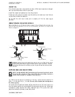
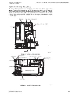
• Drain port
• Seat for measuring draft pressure
• Combustion chamber inspection window
• Combustion monitor
At the points where the flue and smokestack penetrate a wall or ceiling, use a heat-
resisting, fire-proof construction (nonflammable material, such as concrete.
Provide the flue with sufficient support taking its thermal expansion into account. In
addition, provide the flue with a suitable vibration-proof measure. Make sure that the flue
does not apply load to the chiller-heater.
If there is noise concern, consider installing a flue muffler or a smokestack.
Keep the flue openings significantly away from the air inlets of the cooling tower and air
conditioner so that the flue gas does not enter cooling tower, etc. In particular, when the
chiller-heater uses a fuel containing a considerable amount of sulfur (e.g., kerosene oil or a
heavy oil), be sure to install a protective shield or prevent installation of the chiller-heater
and other equipment in the same section enclosed by walls. Make the flue free from entry
of rainwater, snow, etc. In addition, the flue should be constructed so that the ventilation is
not prevented by winds, etc.
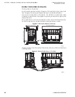
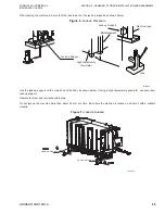
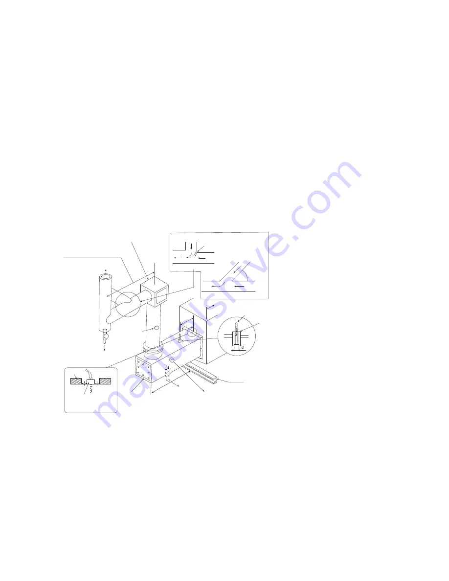
Figure 14 -
Exhaust Gas Flue Diagram
NOTE:
1. The smokestacks box (option) and the flue and instruments after the points of con-
nection with the flue are outside the scope of delivery.
2. Insulate the flue on the basis of 662 °F. to protect from possible burning.
3. Bolts, nuts and packing for fixing the flue are out of scope of delivery. It is the cus-
tomers responsibility to provide these items.
4. For dimensions of the flue connections,
see the Delivery Specifications
in
in this manual.
5. Do not apply flue weight to the chiller-heater.
6.
When insulating the chiller-heater, make sure the soot and dust monitor, draft pres-
sure measuring seat, and the thermometer can be removed and refitted freely.
LD27591
Draft regulator
(Install when the crosscut of gas duct exceeds 3 m
Or the draft power is 49 Pa or more.)
Crosscut should be 3 m or less.
(See note 18.)
To smokestack
Soot and dust monitor
Drain vent
Hot insulation
Exhaust gas temperature relay
Do not embed the relay in the
heat insulation
200
Combustion
chamber inspection
window
Provide the drain port
in the bottom.
To drainage ditch
Drain measuring seat
(Rc 1/2 female)
Set pressure in the range 0 to -49 Pa
Base
Exhaust gas
thermometer
Approximately
10
Exhaust gas
Maximum
45 degrees
Exhaust gas
Arrangement for multiple flue
Exhaust gas
Straightening vane
Exhaust gas
Max
imu
m
1 m
Fix the thermometer
with nonflammable
material (example, asbestos)
Thermometer (out of scope)
Chiller-heater high temperature generator
Arrangement for multiple flue

