JOHNSON CONTROLS
127
SECTION 6 – OPERATION
FORM 155.30-ICOM2.EN.UL
ISSUE DATE: 12/21/2018
6
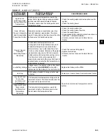
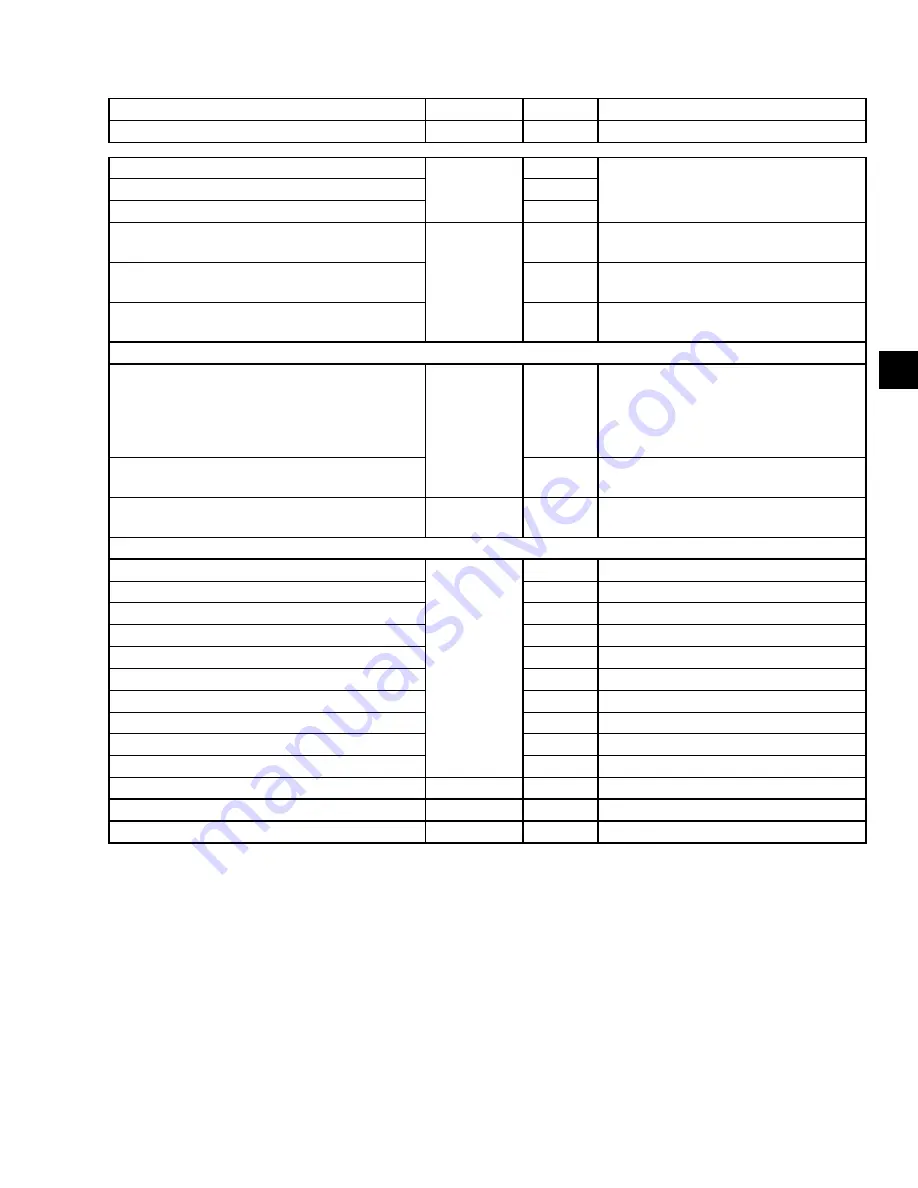
TABLE 27 -
SAFETY SWITCHES
SAFETY SWITCH NAME
LOCATION
SYMBOL
OPERATION
Chilled water differential pressure switch
69WC1
Operates when the flow rate lowers.
Solution circulating pump thermal switch
In control
panel
Th1
Operates when the current rises above the
set value.
Solution spray pump thermal switch
Th2
Refrigerant pump thermal switch
Th3
Chilled water overcooling switch
Soft switch of
sequencer
26WL
Operates when the chilled water outlet
temperature lowers below the set value.
Refrigerant overcooling switch
26RL
Operates when the refrigerant temperature
lowers below the set value.
Solution high temperature switch
26SH1
Operates when the solution temperature in
the generator rises above the set value.
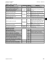
CONTROL SWITCHES:
ON/OFF operation control switch
Soft switch of
sequencer
23AS
Turns OFF when the chilled water
temperature at the outlet lowers below the
set value and turns ON when the chilled
water temperature rises above the set
value.
Purging tank pressure switch
63AP
Operates when the pressure in purging
tank rises above the set value.
Level switch for evaporator tank
Absorption
chiller unit.
LVS
Operates when the refrigerant level in
evaporator is low.
SENSORS AND GAUGES:
Generator pressure gauge
PG1
Purge tank pressure gauge
PG2
Purge tank pressure transmitter
PT1
Detection of pressure of purge tank.
Pt100 Ω for chilled water inlet temperature
TE1
Detection of temperature at each park.
Pt100 Ω for chilled water outlet temperature
TE2
Thermocouple for cooling water inlet temperature
TE3
Thermocouple for cooling water outlet temperature
TE4
Pt100 Ω for refrigerant temperature
TE5
Thermocouple for absorber solution temperature
TE6
Thermocouple for generator solution temperature
TE7
Generator pressure transmitter
PT2
Thermocouple for hot water inlet temperature
TE8
Thermocouple for hot water outlet temperature
TE9

