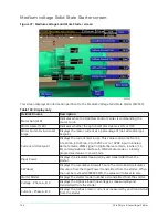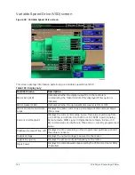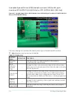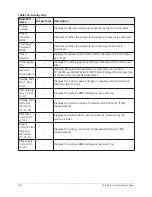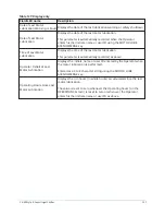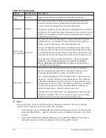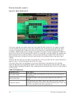
Table 116: Display only
Field/LED name
Description
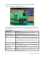
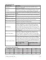
Pre-Rotation Vanes Position Displays the present Pre-Rotation Vane position as a value between
0% (closed) and 100% (full open).
Delta P/P
Displays chiller head pressure calculated as (condenser pressure -
evaporator pressure/evaporator pressure). This value is calculated
by the Microboard.
Temperature Differential
(LCHLT – Setpoint)
Displays the difference between the Leaving Chilled Liquid
Temperature and the Leaving Chilled Liquid Temperature Setpoint.
Command Frequency
This is the speed command being sent to the Drive Logic Board in
either Auto or Manual Speed Control mode.
Speed Decrease Inhibit –
Surge Map Point (LED)
Illuminates when the Microboard ACC function is unable to reduce
speed due to a mapped surge point. Otherwise, it is extinguished.
Mapping Inhibited (LED)
Illuminates when the Microboard ACC function is not permitted to
map points or reduce speed due to unstable Leaving Chilled Liquid
Temperature, manual speed control, current limit in effect (chiller
FLA only) or during Soft Shutdown. Otherwise, it is extinguished.
ACC Surge Detected (LED)
Illuminates momentarily when a surge is detected by the ACC
function in the Microboard, while the drive is running at less than
maximum frequency.
Surge Avoidance Surge
Detected (LED)
Illuminates momentarily when a surge is detected by the Surge
Protection feature. This feature only detects surges that occur while
the drive is running at maximum frequency.
ACC Surge Count
Increments when a surge is detected while the drive is running at
less than maximum frequency.
Surge Map Point Count
Displays the total number of data points contained in the surge
map.
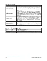
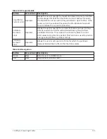
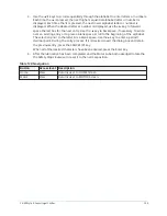
Table 117: Programmable
Button
Description
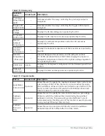
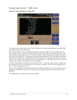
Auto Map Print (Enable/
Disable)
When enabled, the ACC surge map values are printed to a
connected printer each time a surge point is mapped, as shown in
.
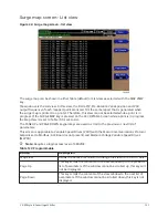
Surge Map Print
Allows the Service Technician to print the entire surge map to a
connected printer, as shown in
Surge Map Clear
Allows the Service Technician to clear the surge map. When this key
is pressed, a dialog box appears requesting a special password to
proceed.
VSD Start Frequency
Sets the starting frequency from which the ramp-up will begin.
Programmable over the following range:
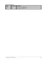
•
60Hz units – 30 Hz to 60 Hz (default 45 Hz)
•
60Hz units with Quick Restart – 30 Hz to 45 Hz (default 45 Hz)
•
50 Hz units – 25 Hz to 50 Hz (default 37.5 Hz)
•
50 Hz units with Quick Restart – 25 Hz to 37.5 Hz (default 37.5
Hz)
117
YK-EP Style B Centrifugal Chiller
Summary of Contents for YK-EP
Page 2: ...2 YK EP Style B Centrifugal Chiller...
Page 6: ...6 YK EP Style B Centrifugal Chiller...
Page 227: ...Figure 72 Sample printout of Status 227 YK EP Style B Centrifugal Chiller...
Page 228: ...Figure 73 Sample printout of Status cont YK EP Style B Centrifugal Chiller 228...
Page 229: ...Figure 74 Sample printout of Setpoints 229 YK EP Style B Centrifugal Chiller...
Page 230: ...Figure 75 Sample printout of Setpoints cont YK EP Style B Centrifugal Chiller 230...
Page 231: ...Figure 76 Sample printout of Schedule 231 YK EP Style B Centrifugal Chiller...
Page 232: ...Figure 77 Sample printout of a Sales order YK EP Style B Centrifugal Chiller 232...
Page 233: ...Figure 78 Sample printout of a Sales order cont 233 YK EP Style B Centrifugal Chiller...
Page 234: ...Figure 79 Sample printout of History YK EP Style B Centrifugal Chiller 234...
Page 235: ...Figure 80 Sample printout of History cont 235 YK EP Style B Centrifugal Chiller...
Page 236: ...Figure 81 Sample printout of a security log report YK EP Style B Centrifugal Chiller 236...


