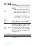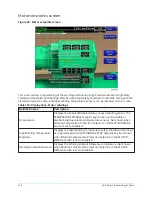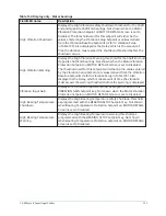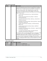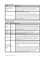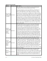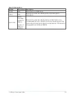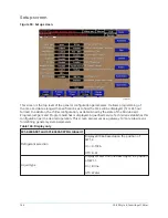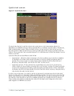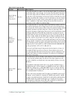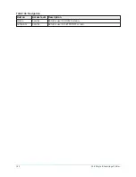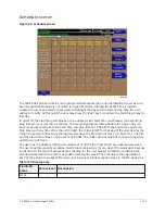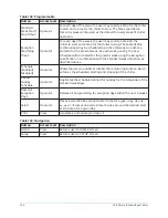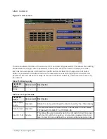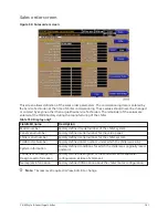
Quick start screen
Figure 51: Quick start screen
The Quick Start feature is useful in data center and process control applications where it is
desirable to re-establish cooling as fast as possible after a shutdown or power failure. This feature,
when enabled, allows quicker starts and restarts than normal control. It does this by reducing
the time cycle for chiller restart and once running, loading the chiller as fast as possible. After the
chiller is running and has met a specified setpoint or a specified period of time has elapsed, control
returns to normal.
Quick Start feature has two different start modes:
•
Quick Restart – When the chiller shuts down, if certain conditions are met at the completion
of coastdown (and within 30 seconds thereafter), the VSD is started immediately with no
prelube. The vanes are given a constant open pulse and after the VSD achieves its start
frequency, the speed ramp rate is faster than with normal control.
•
Quick Normal Start – If the conditions for a Quick Restart are not met, the next time the
chiller is started, it has a prelube period just like a normal start, however the vanes will begin
to open at the beginning of prelube, instead of waiting until System Run. At the completion
of prelube, the VSD is started and after the VSD achieves its Start Frequency, the speed ramp
rate is faster than with normal control.
In order to use this feature, the chiller must be equipped with a Variable Speed Drive in Modbus
Protocol Configuration or a Medium Voltage Variable Speed Drive. The low inrush current of a VSD
allows more starts per hour and allows the chiller to start with a more open vane position. It must
be enabled on the Setpoints Screen with an ADMIN password by a qualified Service Technician.
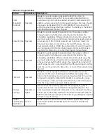
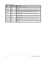
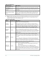
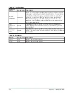
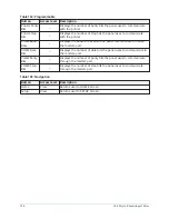
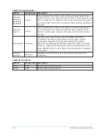
Once enabled, all setpoints and parameters related to this feature are displayed on this screen,
when logged in at SERVICE access level.
149
YK-EP Style B Centrifugal Chiller
Summary of Contents for YK-EP
Page 2: ...2 YK EP Style B Centrifugal Chiller...
Page 6: ...6 YK EP Style B Centrifugal Chiller...
Page 227: ...Figure 72 Sample printout of Status 227 YK EP Style B Centrifugal Chiller...
Page 228: ...Figure 73 Sample printout of Status cont YK EP Style B Centrifugal Chiller 228...
Page 229: ...Figure 74 Sample printout of Setpoints 229 YK EP Style B Centrifugal Chiller...
Page 230: ...Figure 75 Sample printout of Setpoints cont YK EP Style B Centrifugal Chiller 230...
Page 231: ...Figure 76 Sample printout of Schedule 231 YK EP Style B Centrifugal Chiller...
Page 232: ...Figure 77 Sample printout of a Sales order YK EP Style B Centrifugal Chiller 232...
Page 233: ...Figure 78 Sample printout of a Sales order cont 233 YK EP Style B Centrifugal Chiller...
Page 234: ...Figure 79 Sample printout of History YK EP Style B Centrifugal Chiller 234...
Page 235: ...Figure 80 Sample printout of History cont 235 YK EP Style B Centrifugal Chiller...
Page 236: ...Figure 81 Sample printout of a security log report YK EP Style B Centrifugal Chiller 236...

