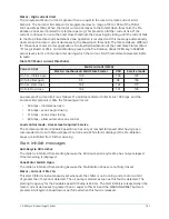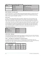
Table 199: Manual and automatic shutdown resets
Device
Manual reset fault
Automatic reset fault
Overload
None
CM-2 Module
Overload
Phase Rotation/Loss
High Temp (more than 212°F)
High Temp start inhibit (more than 110°F)
Solid State Starter
Fault Current
Trigger Board Out-of-Lock
Motor Controller – Loss Of Current
The Compressor Motor current decreased to 10% Full Load Amps (FLA) for 25 continuous seconds
while the chiller was running. This could be caused by the starter de-energizing during run or a
defect in the motor current feedback circuitry to the Control Center. The chiller will automatically
restart at the completion of System Coastdown.
Power Fault
The CM-2 Current Module (Electro-Mechanical Starter applications) or Solid State Starter Logic
Board (Mod “A” Solid State Starter applications) has shutdown the chiller because it detected a
fault condition that places the motor at risk. These devices open and close the Motor Controller
“CM” contacts (located on the respective device and connected between TB6-16 and TB6-53 in the
Control Center) in less than 3 seconds to initiate the shutdown and produce this message. An LED
on the respective device illuminates to identify the specific fault that has occurred. Refer to
Solid
State Starter (Mod “A”) – Operation and Maintenance (Form 160.46-OM3.1)
for details of Solid State
Starter initiated shutdowns and
OptiView Control Center – Service Instructions (Form 160.54-M1)
for
CM-2 initiated shutdowns. The chiller will automatically restart when the contacts close.
Table 200: Device shutdown
Device
Shutdown
CM-2 Module
Power Fault
Solid State Starter
Power Fault
Half Phase
Control Panel – Schedule
The programmed Daily Schedule Setpoint has shutdown the chiller. If this occurs while the chiller is
running, the Pre-Rotation Vanes are driven fully closed prior to shutting down the chiller. The chiller
will automatically restart at the next scheduled start time.
Starter – Low Supply Line Voltage (Mod “A” Solid State Starter)
The voltage in any phase of the AC Power Line Voltage supplying the Solid State Starter has
decreased to the low line voltage threshold for 20 continuous seconds. The chiller will automatically
restart when the voltage returns to the restart level. The thresholds are as follows:
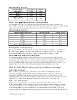
Table 201: Voltage thresholds
Supply voltage
range (Volts)
Shutdown
(volts)
Restart
(volts)
380
305
331
400
320
349
415
335
362
YK-EP Style B Centrifugal Chiller
198
Summary of Contents for YK-EP
Page 2: ...2 YK EP Style B Centrifugal Chiller...
Page 6: ...6 YK EP Style B Centrifugal Chiller...
Page 227: ...Figure 72 Sample printout of Status 227 YK EP Style B Centrifugal Chiller...
Page 228: ...Figure 73 Sample printout of Status cont YK EP Style B Centrifugal Chiller 228...
Page 229: ...Figure 74 Sample printout of Setpoints 229 YK EP Style B Centrifugal Chiller...
Page 230: ...Figure 75 Sample printout of Setpoints cont YK EP Style B Centrifugal Chiller 230...
Page 231: ...Figure 76 Sample printout of Schedule 231 YK EP Style B Centrifugal Chiller...
Page 232: ...Figure 77 Sample printout of a Sales order YK EP Style B Centrifugal Chiller 232...
Page 233: ...Figure 78 Sample printout of a Sales order cont 233 YK EP Style B Centrifugal Chiller...
Page 234: ...Figure 79 Sample printout of History YK EP Style B Centrifugal Chiller 234...
Page 235: ...Figure 80 Sample printout of History cont 235 YK EP Style B Centrifugal Chiller...
Page 236: ...Figure 81 Sample printout of a security log report YK EP Style B Centrifugal Chiller 236...

