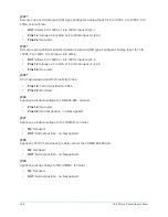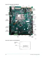
JP15
Applies a pull-up voltage to the COM3 + terminal.
•
IN:
Not used.
•
OUT:
Normal position - no bias applied.
JP16
Applies a pull-down voltage to the COM2 - terminal.
•
IN:
Not used.
•
OUT:
Normal position - no bias applied.
JP17
Applies a pull-up voltage to the COM2 + terminal.
•
IN:
Not used.
•
OUT
: Normal position - no termination applied.
JP18
Applies a 120 Ohm terminating resistor
•
IN:
Not used.
•
OUT:
Normal position - no bias applied.
JP19
Applies a pull-up voltage to the COM2 + terminal.
•
IN:
Not used.
•
OUT:
Normal position - no bias applied.
JP20
Applies a pull-down voltage to the COM3 - terminal.
•
IN:
Not used.
•
OUT:
Normal position - no bias applied.
JP21*
Shunt must be removed or hang on one pin
•
Pins 1-2:
Not used
•
Pins 2-3:
Not used
JP22*
Shunt must be removed or hang on one pin
•
Pins 1-2:
Not used.
•
Pins 2-3:
Not used.
245
YK-EP Style B Centrifugal Chiller
Summary of Contents for YK-EP
Page 2: ...2 YK EP Style B Centrifugal Chiller...
Page 6: ...6 YK EP Style B Centrifugal Chiller...
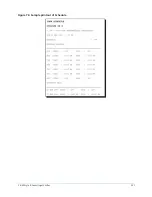
Page 227: ...Figure 72 Sample printout of Status 227 YK EP Style B Centrifugal Chiller...
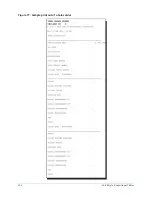
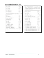
Page 228: ...Figure 73 Sample printout of Status cont YK EP Style B Centrifugal Chiller 228...
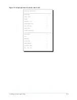
Page 229: ...Figure 74 Sample printout of Setpoints 229 YK EP Style B Centrifugal Chiller...
Page 230: ...Figure 75 Sample printout of Setpoints cont YK EP Style B Centrifugal Chiller 230...
Page 231: ...Figure 76 Sample printout of Schedule 231 YK EP Style B Centrifugal Chiller...
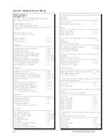
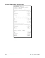
Page 232: ...Figure 77 Sample printout of a Sales order YK EP Style B Centrifugal Chiller 232...
Page 233: ...Figure 78 Sample printout of a Sales order cont 233 YK EP Style B Centrifugal Chiller...
Page 234: ...Figure 79 Sample printout of History YK EP Style B Centrifugal Chiller 234...
Page 235: ...Figure 80 Sample printout of History cont 235 YK EP Style B Centrifugal Chiller...
Page 236: ...Figure 81 Sample printout of a security log report YK EP Style B Centrifugal Chiller 236...

