from either VSD type, the microboard will “remember” this, even after a power failure. This allows
the correct screens to be displayed after a power failure, without repeating the poll interrogation
as long as the Motor Drive Type is not changed. Once the microboard determines which VSD type is
connected, it will not poll for the other.
Medium Voltage Solid State Starter (MV SSS) and Medium Voltage Variable
Speed Drive interface (MV VSD)
These drives communicate with the microboard via the COM2 RS-485 Modbus serial port (J13).
Refer to
Medium Voltage Solid State Starter – Service (Form 160.00-M5)
and
Medium Voltage Variable
Speed Drive – Service (Form 160.00-M6)
for details of this interface. When the MV SSS or MV VSD is
selected on the SETUP Screen, the COM2 serial port with Modbus protocol is automatically enabled.
With the MV VSD, the Adaptive capacity Control functionality is contained on the microboard.
Printer interface
An optional printer can be connected to COM1 RS-232 serial data port (J2). TX data to the printer
is at J2-4. The DSR (Data Set Ready or busy) signal from the printer is at J2-2. Signal levels are
standard RS-232. The microboard sends data to the printer at the selected baud rate until the
printer buffer becomes full, where-upon the printer asserts its Busy signal. The microboard
suspends data transmission until the printer can accept more data. Each printer must be setup/
configured to operate properly with the microboard. The Baud, Data Bits, Parity and Stop Bits must
be programmed on the COMMS Screen. Other printer setup is performed on the Printer Screen.
SC-EQ communications interface card
An optional SC-EQ communication card can be connected to the COM 4B RS-232 serial data port
(J2). TX data to the SC-EQ is at J2-7. RX data from the SC-EQ is at J2-6. Signal levels are standard
RS-232. The SC-EQ polls system pressures, temperatures and status from the microboard. It holds
it for retrieval by third-party devices. Refer to
SC-EQ Installation Instructions (Form 450.50-N1)
for
details on the SC-EQ (Smart Chiller - Equipment) communications card.
Digital inputs
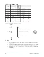
The I/O Board converts the 115VAC inputs to logic level inputs for the microboard at J19. A 115VAC
input to the I/O Board is converted to a logic low (less than 1VDC). A 0VAC input to the I/O Board is
converted to a logic high (greater than 4VDC). Refer to
Form 160.54-M1
for more details on the I/O
board.
Digital outputs
The microboard controls 115VAC relays and solenoids via the I/O Board (via J19). The I/O Board
co12VDC relays that isolate the microboard low voltage circuits from the 115VAC device
coils. Solid state switching devices are used to control the relays. The microboard energizes the
+12VDC relays by applying a ground to the coil input. They are de-energized by opening the ground
path. The contacts of these relays switch 115VAC to system relays and solenoids. The outputs that
control the chilled liquid pump and compressor motor starter have anti-chatter (anti-recycle) timers
associated with them. The output that controls relay K0 is not allowed to change at a rate greater
than once every 10 seconds. The output that controls relay K13 is not allowed to change at a rate
greater than once every 20 seconds.
The microboard controls actuator motors via Triacs on the I/O Board. Each actuator has an open
winding and a close winding. Current flowing through a winding causes the actuator to rotate
in the respective direction. Each winding is controlled by a Triac. The Triac is turned ON to allow
current to flow through a winding. The microboard turns on the Triac by applying a logic low (less
than 1VDC) to the Triac driver on the I/O Board. It turns it OFF by applying a logic high (greater
than 4VDC).
249
YK-EP Style B Centrifugal Chiller
Summary of Contents for YK-EP
Page 2: ...2 YK EP Style B Centrifugal Chiller...
Page 6: ...6 YK EP Style B Centrifugal Chiller...
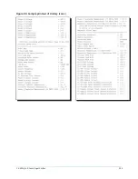
Page 227: ...Figure 72 Sample printout of Status 227 YK EP Style B Centrifugal Chiller...
Page 228: ...Figure 73 Sample printout of Status cont YK EP Style B Centrifugal Chiller 228...
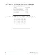
Page 229: ...Figure 74 Sample printout of Setpoints 229 YK EP Style B Centrifugal Chiller...
Page 230: ...Figure 75 Sample printout of Setpoints cont YK EP Style B Centrifugal Chiller 230...
Page 231: ...Figure 76 Sample printout of Schedule 231 YK EP Style B Centrifugal Chiller...
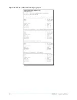
Page 232: ...Figure 77 Sample printout of a Sales order YK EP Style B Centrifugal Chiller 232...
Page 233: ...Figure 78 Sample printout of a Sales order cont 233 YK EP Style B Centrifugal Chiller...
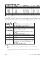
Page 234: ...Figure 79 Sample printout of History YK EP Style B Centrifugal Chiller 234...
Page 235: ...Figure 80 Sample printout of History cont 235 YK EP Style B Centrifugal Chiller...
Page 236: ...Figure 81 Sample printout of a security log report YK EP Style B Centrifugal Chiller 236...

