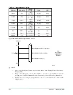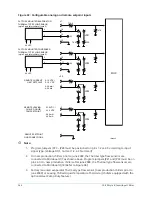
Note:
1. On new production chillers after June 2009, the Thermal type flow sensors are connected
to Microboard J14 as shown above. Program Jumpers JP10 through JP12 must be
positioned on pins 2-3 and software version C.OPT.01.21.307 (and later) is required. On
new production chillers prior to June 2009, the Thermal type flow sensors are connected
to Microboard J7 (Refer to Figure 92).
267
YK-EP Style B Centrifugal Chiller
Summary of Contents for YK-EP
Page 2: ...2 YK EP Style B Centrifugal Chiller...
Page 6: ...6 YK EP Style B Centrifugal Chiller...
Page 227: ...Figure 72 Sample printout of Status 227 YK EP Style B Centrifugal Chiller...
Page 228: ...Figure 73 Sample printout of Status cont YK EP Style B Centrifugal Chiller 228...
Page 229: ...Figure 74 Sample printout of Setpoints 229 YK EP Style B Centrifugal Chiller...
Page 230: ...Figure 75 Sample printout of Setpoints cont YK EP Style B Centrifugal Chiller 230...
Page 231: ...Figure 76 Sample printout of Schedule 231 YK EP Style B Centrifugal Chiller...
Page 232: ...Figure 77 Sample printout of a Sales order YK EP Style B Centrifugal Chiller 232...
Page 233: ...Figure 78 Sample printout of a Sales order cont 233 YK EP Style B Centrifugal Chiller...
Page 234: ...Figure 79 Sample printout of History YK EP Style B Centrifugal Chiller 234...
Page 235: ...Figure 80 Sample printout of History cont 235 YK EP Style B Centrifugal Chiller...
Page 236: ...Figure 81 Sample printout of a security log report YK EP Style B Centrifugal Chiller 236...


