as 45.0°F for the Leaving Chilled Liquid Temperature), or they could enable or disable a feature or
function.
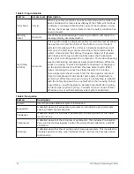
Regardless of which setpoint is being programmed, the following procedure applies:
1. Press the desired setpoint key. A dialog box appears displaying the present value, the upper
and lower limits of the programmable range, and the default value.
2. If the dialog box begins with the word ENTER, use the numeric keys to enter the desired
value. Leading zeroes are not necessary. If a decimal point is necessary, press the ‘•’ key (i.e.
45.0).
Pressing the ▲ key, sets the entry value to the default for that setpoint. Pressing the ▼ key,
clears the present entry. The ◄ key is a backspace key and causes the entry point to move
back one space.
If the dialog box begins with SELECT, use the ◄ and ► keys to select the desired value.
If the previously defined setpoint is desired, press the ‘X’ (Cancel) key to dismiss the dialog
box.
3. Press the
Enter
key.
4. If the value is within range, it is accepted and the dialog box disappears. The chiller will
begin to operate based on the new programmed value. If out of range, the value will not be
accepted and the user is prompted to try again.
Manual controls
Some keys are used to perform manual control functions. These may involve manual control of
items such as the Pre-Rotation Vanes, variable orifice or oil pump speed. Other keys in this category
are used to initiate/terminate processes such as calibrations or reports.
Free cursor
On screens containing many setpoints, a specific SOFT key may not be assigned to each setpoint
value. A SOFT key will be assigned to enable the cursor arrow keys below the numeric keypad which
are used to HIGHLIGHT the desired setpoint field. At this point, the Enter key is pressed to bring up
a dialog prompting the user to enter a new setpoint value. The (X) key cancels cursor mode. (Refer
to
for an example.)
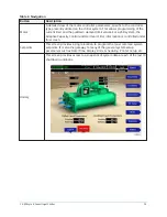
Navigation
In order to maximize the amount of values which the panel can display to the user, and in order
to place those values in context, multiple screens have been designed to describe the chiller
operation. In order to move from one screen to the next, navigation keys have been defined.
These keys allow the user to either move FORWARD to a subscreen of the present screen, or move
BACKWARD to the previous screen. Except for the HOME Screen display, the upper-right SOFT key
will always return the user to the HOME Screen. Navigating with SOFT keys is as simple as pressing
the key next to the label containing the name of the desired screen. The system will immediately
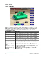
refresh the display with the graphics for that screen. This list shows a layout of all the screens and
how they are connected from the Home screen.
•
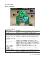
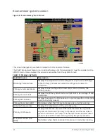
System screen
- Economizer screen
•
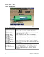
Evaporator screen
•
Condenser screen
- Refrigerant level control screen
YK-EP Style B Centrifugal Chiller
18
Summary of Contents for YK-EP
Page 2: ...2 YK EP Style B Centrifugal Chiller...
Page 6: ...6 YK EP Style B Centrifugal Chiller...
Page 227: ...Figure 72 Sample printout of Status 227 YK EP Style B Centrifugal Chiller...
Page 228: ...Figure 73 Sample printout of Status cont YK EP Style B Centrifugal Chiller 228...
Page 229: ...Figure 74 Sample printout of Setpoints 229 YK EP Style B Centrifugal Chiller...
Page 230: ...Figure 75 Sample printout of Setpoints cont YK EP Style B Centrifugal Chiller 230...
Page 231: ...Figure 76 Sample printout of Schedule 231 YK EP Style B Centrifugal Chiller...
Page 232: ...Figure 77 Sample printout of a Sales order YK EP Style B Centrifugal Chiller 232...
Page 233: ...Figure 78 Sample printout of a Sales order cont 233 YK EP Style B Centrifugal Chiller...
Page 234: ...Figure 79 Sample printout of History YK EP Style B Centrifugal Chiller 234...
Page 235: ...Figure 80 Sample printout of History cont 235 YK EP Style B Centrifugal Chiller...
Page 236: ...Figure 81 Sample printout of a security log report YK EP Style B Centrifugal Chiller 236...

