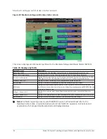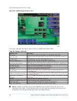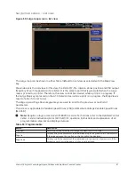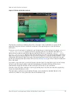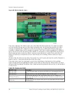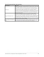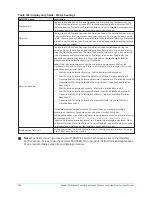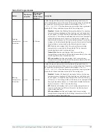
Adaptive Capacity Control details screen
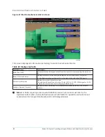
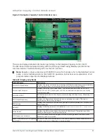
Figure 53: Adaptive Capacity Control details screen
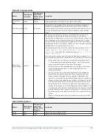
This screen displays detailed information pertaining to the Adaptive Capacity Control (ACC).
The Microboard communicates directly with the VSD Logic Board using Modbus protocol serial
communications. The Microboard performs the ACC function.
Note:
Requires a login access level of SERVICE. Service Technicians refer to the
OptiView Control
Center - Service Instructions (Form 160.76-M1)
for operation instructions and explanation of all
programmable setpoints and displayed values.
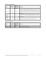
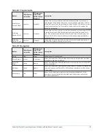
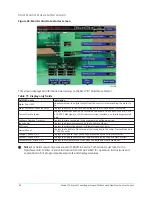
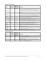
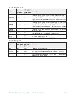
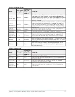
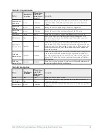
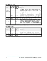
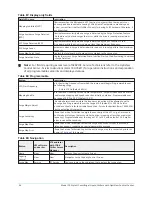
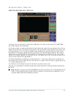
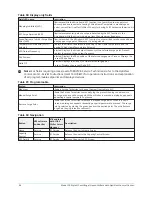
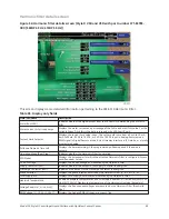
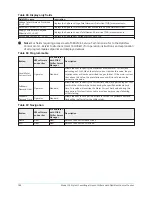
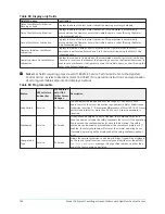
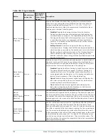
Table 87: Display only fields
Field/LED name
Description
Motor % Full Load Amps
Displays the motor current as a percentage of chiller Full Load Amps as calculated by
the microboard from current values returned from the drive Logic Board.
Current Limit Setpoint
Displays the current limit value in use. This value could come from a 0 mA to 20
mA, 0 VDC to 10 VDC, PWM signal, or SC-EQ communication interface, or a locally
programmed value.
Motor Run (LED)
Illuminated when the Control Center is commanding the drive to run. Otherwise, it is
extinguished.
VSD Output Frequency
Displays the frequency at which the drive is operating the motor. This value is
returned from the drive Logic Board.
PRV Position
Displays the present pre-rotation vane position as a value between 0% (closed) and
100% (full open).
Delta P/P
Displays chiller head pressure calculated as
condenser pressure - evaporator
pressure/evaporator pressure
.
Active Delta T
Displays the difference between the Leaving Chilled Liquid Temperature and the
Leaving Chilled Liquid Temperature Setpoint.
VSD Frequency Command
This is the speed command being sent to the Drive Logic Board in either Auto or
Manual Speed Control mode.
Speed Decrease Inhibit – Surge Map
Point (LED)
Illuminates when the Microboard ACC function is unable to reduce speed due to a
mapped surge point. Otherwise, it is extinguished.
93
Model YK Style H Centrifugal Liquid Chillers with OptiView Control Center

