FORM 160.52-M2
YORK INTERNATIONAL
13
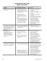
TROUBLESHOOTING GUIDE
(MOD D CHILLERS)
PROBLEM
MEASUREMENTS REQUIRED
SOLUTION
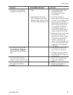
Blown Input Fuses or the status
1. Remove input wires, L1-L3
1. (a) If input is shorted, replace
LED is not lit.
from the VSOP drive, measure
VSOP drive.
resistance, input phase to phase
1. (b) If input is not shorted,
on the VSOP drive.
replace L1–L3 and continue to the
next step.
2. Remove wires M1-M3,
2. (a) If output is shorted, replace
measure resistance, output
VSOP drive.
phase to phase on the VSOP
2. (b) If output is not shorted, replace
drive.
M1-M3, and continue to next step.
3. Inspect components on VSOP
3. (a) If any components are
drive output filter board. Remove
visibly damaged, replace
T1-T3 wires from VSOP drive
VSOP drive output filter board.
output filter board. Measure
3. (b) If any shorts or opens are
resistance phase to phase.
detected, replace VSOP drive
output filter board.
4. Replace the blown input fuses.
Status display on the Microcomputer
1. Refer to the Auto Re-settable and
1. Correct for any of the fault
Control Center reads OIL PUMP
Non-Re-settable shutdowns in the
conditions in the previous section.
DRIVE–AUTOSTART, and the status
previous section.
LED is flashing RED on the
VSOP drive.
Status display on the
1. Measure voltage between
1. (a) If 0 VAC is measured,
Microcomputer Control Center
terminal #1on the VSOP drive
replace VSOP drive.
reads OIL PUMP DRIVE –
and Ground.
1. (b) If 115 VAC is measured,
AUTOSTART, but the status
continue to the next step.
LED is a constant RED on the.
2. Measure voltage between TB1-
2. (a) If 0 VAC is measured, verify
VSOP drive.
70 on the digital input board
wiring between terminal #1 on
and ground.
the VSOP and TB1-70.
Replace wire if required.
2. (b) If wiring is okay, verify operation
of the digital input board and
Microcomputer Control Center.
Replace parts as needed.
Trying to start the VSOP drive, but
1. Measure voltage between terminal
1. (a) If 0 VDC is displayed, verify
the VSOP drive will not start and the
V+ on the VSOP drive and ground
wiring from V+ to the power
status LED is a constant RED.
on the power supply board.
supply board.
1. (b) If 12 VDC is measured,
continue to the next step.
2. Manually start the VSOP drive from
2. (a) If 12 VDC is displayed, verify
the Microcomputer Control Center.
wiring from EN to the power supply
Measure voltage between terminal
board.
EN on the VSOP drive and ground.
2. (b) If 0 VDC is measured,
continue to the next step.
3. Remove wire #29 from TB3 on the
3. (a) If VSOP drive starts, verify
relay output board and connect to
wiring to relay output board and
wire #1.
micro board.
3. (b) If VSOP drive does start,
replace 3R. If VSOP drive still does
not start, replace VSOP drive.


