JOHNSON CONTROLS
FORM 160.75-EG1 (519)
46
Application Data (Cont'd)
Oil Pump Power Supply
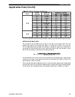
– A separate 3 phase power supply with a fused disconnect for
the factory-mounted oil pump variable speed drive is required unless the low voltage VSD
or SSS is supplied. Power can also be supplied through an electromechanical starter, re-
mote mounted Medium Voltage Solid-State Starter (MV SSS) or Medium Voltage Variable
Speed Drive (MV VSD).
Copper Conductors
– Only copper conductors should be connected to compressor mo-
tors and starters. Aluminum conductors have proven to be unsatisfactory when connected
to copper lugs. Aluminum oxide and the difference in thermal conductivity between copper
and aluminum cannot guarantee the required tight connection over a long period of time.
Displacement Power-factor Correction Capacitors
– When the chiller is equipped
with a VSD, automatic displacement power factor correction to a minimum of 0.95 is pro-
vided at all operating conditions, so additional capacitors are not required. For other start-
ing methods, capacitors can be applied to a chiller for the purpose of displacement power
factor correction. For remote-mounted electromechanical starters, the capacitors should
be located on the load side of the starter. For YORK
®
Solid-State Starters the capacitors
must be located on the line side of the starter. The capacitors must be sized and installed
to meet the National Electrical Code and be verified by Johnson Controls.
Ampacity on Load Side of Starter
– Electrical power wire size to the chiller is based on
the minimum unit ampacity. For Solid-State Starters or Variable Speed Drive, this wiring
is done at the factory. For remote starters, the National Electrical Code defines the calcu-
lation of ampacity, as summarized below. More specific information on actual amperage
ratings will be supplied with the submittal drawings:
• Six lead type of starting (Star Delta) Minimum circuit ampacity per conductor (1 of 6):
Ampacity =
721 x compressor motor amps
• Three lead type of starting (Across the Line, Autotransformer and Primary Reactor)
Minimum circuit ampacity per conductor (1 of 3): Ampacity = 1.25 x compressor mo-
tor amps.
Ampacity on Line Side of Starter
– The only additional load on the circuit for the chiller
would be the control transformer and oil pump motor unless they are supplied by a sepa-
rate source.
Minimum Circuit Ampacity = 125% of compressor motor amps
+ FLA of all other loads on the circuit
Branch Circuit Overcurrent Protection
– The branch circuit overcurrent protection de-
vices should be a time delay type, with a minimum rating equal to the next standard fuse/
breaker rating above the calculated value. It is calculated taking into account the com-
pressor motor amps and may also include control transformer and oil pump motor. Refer
to submittal drawings for the specific calculations for each application. See
Voltage Variable Speed Models on page 65
.
Summary of Contents for YK
Page 4: ...JOHNSON CONTROLS FORM 160 75 EG1 519 4 THIS PAGE INTENTIONALLY LEFT BLANK...
Page 18: ...JOHNSON CONTROLS FORM 160 75 EG1 519 18 THIS PAGE INTENTIONALLY LEFT BLANK...
Page 59: ...FORM 160 75 EG1 519 JOHNSON CONTROLS 59 THIS PAGE INTENTIONALLY LEFT BLANK...
Page 83: ...FORM 160 75 EG1 519 JOHNSON CONTROLS 83 THIS PAGE INTENTIONALLY LEFT BLANK...
Page 91: ...FORM 160 75 EG1 519 JOHNSON CONTROLS 91 THIS PAGE INTENTIONALLY LEFT BLANK...
Page 113: ...FORM 160 75 EG1 519 JOHNSON CONTROLS 113 THIS PAGE INTENTIONALLY LEFT BLANK...


