JOHNSON CONTROLS
129
SECTION 7 – UNIT CONTROLS
FORM 150.72-ICOM6
ISSUE DATE: 08/03/2022
7
Unit Warning
The following messages are not unit safeties and will
not be logged to the history buffer. They are unit warn-
ings and will not auto-restart. Operator intervention is
required to allow a restart of the chiller.
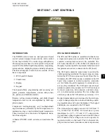
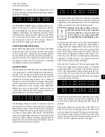
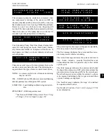
! ! L O W B A T T E R Y ! !
C H E C K P R O G / S E T P / O P T N
The Low Battery Warning can only occur at unit pow-
er-up. On micro panel power-up, the RTC battery is
checked. If a low battery is found, all programmed
setpoints, program values, options, time, schedule,
and history buffers will be lost. These values will all
be reset to their default values which may not be the
required operating values. Once a faulty battery is de-
tected, the unit will be prevented from running until
the PROGRAM key is pressed. Once PROGRAM is
pressed the anti-recycle timers will be set to the pro-
grammed anti-recycle time to allow the operator time
to check setpoints, and if necessary, reprogram pro-
grammable values and options.
If a low battery is detected, it should be replaced as
soon as possible. The programmed values will all be
lost and the unit will be prevented from running on the
next power interruption. The RTC/battery (031-02565-
000) is located at U5 on the microboard.
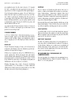
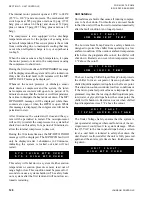
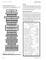
I N C O R R E C T
U N I T T Y P E
This indicates the condensing unit jumper is installed
between J11-12 and J11-7. This jumper must be re-
moved to operate the chiller.
Resetting System Lockout Faults
If three faults on the same system occur within 90 min-
utes, that system will be locked out on the last fault.
This condition requires a manual reset. The system
switch (under OPTIONS key) must be turned off and
then back on to clear the lockout fault. Fault messages
will be displayed whenever a system is locked out.
System Safety
Discharge Pressure Cutout
When the operating envelope is disabled, the discharge
pressure cutout is the programmable cutout.
When the operating envelope is a standard operating
envelope and the suction pressure is less than 94.0
psig, the discharge pressure cutout will be set to 10
psig above the discharge pressure unload limit.
When the operating envelope is an extended operat-
ing envelope and the suction pressure is less than 42.0
psig, the discharge pressure cutout will be set to 10
psig above the discharge pressure unload limit.
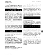
The system will shut down when the discharge pres-
sure cutout, as determined above, is exceeded. The sys-
tem can be restarted when the discharge pressure falls
below the cutout of minus 40 psig.
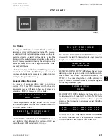
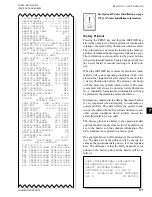
S Y S 1 H I G H D S C H P R E S
S Y S 2 H I G H D S C H P R E S
Suction Pressure Cutout
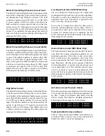
The Suction Pressure Cutout protects the chiller from
an evaporator freeze-up should the system attempt to
run with a low refrigerant charge. Following are the
messages for both systems.
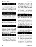
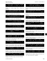
S Y S 1 L O W S U C T P R E S S
S Y S 2 L O W S U C T P R E S S
At system start, the cutout is set to 10% of programmed
value. During the next 3 minutes the cutout point is
ramped up to the programmed cutout point. If at any
time during the 3 minutes the suction pressure falls be-
low the ramped cutout point, the system will stop. This
cutout is completely ignored for the first 30 seconds of
system run time to avoid nuisance shutdowns, espe-
cially on units with a low pressure switch.
After the first 3 minutes, if the suction pressure falls
below the programmed cutout setting, a transient pro-
tection routine is activated. This sets the cutout at 10%
of the programmed value and ramps up the cutout
over the next 30 seconds. If at any time during the 30
seconds the suction pressure falls below the ramped
cutout, the system will stop. This transient protection
scheme only works if the suction pressure transducer
is installed.

