Johnson Controls
44
Form 150.72-ICOM6
Issue date: 12/19/2023
Section 4: Installation
Thermal dispersion flow switch
1. Thermal Dispersion Flow Switch Operating
Principle
The operating principle of the thermal dispersion
flow switch is based on the calorimetric princi-
ple. It uses the cooling effect of a flowing fluid
to monitor the flow rate. The amount of thermal
energy that is removed from the tip determines the
local flow rate. This temperature-based operating
principle can reliably sense the flow of virtually
any liquid or gas.
The sensor tip of the thermal dispersion flow sen-
sor houses two transistors and a heater element.
One transistor is located in the sensor tip, closest
to the flowing fluid. This transistor is used to de-
tect changes in the flow velocity of the liquid. The
second transistor is bonded to the cylindrical wall
and is a reference for ambient fluid conditions.
In order to make the sensor sense flow, it is nec-
essary to heat one of the transistors in the probe.
When power is applied, the tip of the probe is
heated. As the fluid starts to flow, heat will be
carried away from the sensor tip. Cooling of the
first transistor is a function of how fast heat is
conducted away by the flowing liquid. The dif-
ference in temperature between the two transis-
tors provides a measurement of fluid velocity past
the sensor probe. When fluid velocity is high, the
temperature differential is small. As fluid velocity
decreases, there is an increase in the temperature
differential.
2. Service Information
The P/N of the thermal dispersion switch is 025-
43553-000, SAP # is 618247. you can purchase
it from JCI part center through JCI service office
close to your site.
The connection of thermal dispersion switch is
1/4 in. NPT, so when replacing a flow switch with
different connection size, the connector on the liq-
uid system need to replace as well so that it can
adapt to the thermal dispersion flow switch.
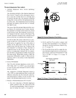
3. Wiring of Thermal Dispersion Flow Switch
a. The wire connection of thermal dispersion
switch contains 5 pins, the central pin is Pin
#5 used for programming, which is unneces-
LD21044
PIN NUMBERS
Figure 12:
Thermal Dispersion Flow Switch
b. Pin #1 and Pin #3 are used to connect with
24 VAC from transformer T1 by terminal #
40 and 41. (see the red dot line frame in
)
c. Pin #2 and Pin #4 are used to output the sta-
tus of thermal dispersion flow switch, these 2
pins need to connected with terminal #13 and
indicated.
LD21045
ELECTRICAL DIAGRAM
NO FLOW
PROGRAMMING
PIN
DIGITAL OUTPUT
24VAC
+5V DC
L +
L -
1
5
2
4
3
Figure 13:
Wiring of Thermal Dispersion Flow Switch


