background image

20

JOHNSON CONTROLS

 FORM 150.63-EG4 (1012)

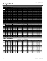
Ratings 50Hz SI

MODEL: YLUA0248YE

 AIR TEMPERATURE ON - CONDENSER (°C)

25.0

30.0

35.0

40.0

45.0

KW

KW

COP

KW

KW

COP

KW

KW

COP

KW

KW

COP

KW

KW

COP

2.0

228.9

49.2

4.1

217.5

54.5

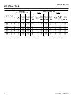
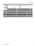
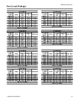
3.6

205.3

60.6

3.1

190.3

66.9

2.6

174.8

73.7

2.2

3.0

236.1

49.5

4.2

224.4

54.9

3.6

211.8

61.0

3.1

196.5

67.3

2.7

180.6

74.2

2.2

4.0

243.5

50.0

4.3

231.4

55.3

3.7

218.5

61.4

3.2

202.8

67.7

2.7

186.4

74.7

2.3

5.0

251.0

50.4

4.4

238.6

55.7

3.8

225.4

61.8

3.3

209.2

68.2

2.8

192.4

75.1

2.4

6.0

258.6

50.8

4.5

245.9

56.1

3.9

232.3

62.2

3.4

215.7

68.6

2.9

198.5

75.6

2.4

7.0

266.4

51.3

4.6

253.4

56.6

4.0

239.4

62.7

3.5

222.4

69.0

2.9

204.7

76.0

2.5

8.0

274.3

51.8

4.7

260.9

57.0

4.1

246.6

63.1

3.5

229.2

69.5

3.0

211.0

76.5

2.5

9.0

282.3

52.3

4.8

268.6

57.5

4.2

254.0

63.6

3.6

236.1

70.0

3.1

217.5

77.0

2.6

10.0

290.5

52.8

4.9

276.5

58.0

4.3

261.5

64.1

3.7

243.1

70.5

3.2

224.1

77.5

2.7

11.0

298.8

53.4

5.0

284.5

58.6

4.4

269.1

64.6

3.8

250.3

71.0

3.2

230.7

78.0

2.7

12.0

307.3

54.0

5.1

292.6

59.1

4.4

276.8

65.2

3.9

257.6

71.5

3.3

237.5

78.5

2.8

MODEL: YLUA0278YE

 AIR TEMPERATURE ON - CONDENSER (°C)

25.0

30.0

35.0

40.0

45.0

KW

KW

COP

KW

KW

COP

KW

KW

COP

KW

KW

COP

KW

KW

COP

2.0

240.0

55.4

3.9

227.8

61.4

3.3

214.7

68.2

2.9

198.9

75.3

2.4

182.5

83.0

2.0

3.0

247.5

55.8

4.0

235.0

61.9

3.4

221.6

68.7

2.9

205.3

75.8

2.5

188.4

83.5

2.1

4.0

255.1

56.3

4.1

242.3

62.3

3.5

228.5

69.2

3.0

211.8

76.3

2.6

194.5

84.1

2.1

5.0

262.9

56.8

4.1

249.8

62.8

3.6

235.7

69.7

3.1

218.5

76.8

2.6

200.7

84.6

2.2

6.0

270.9

57.3

4.2

257.4

63.3

3.7

242.9

70.2

3.2

225.3

77.4

2.7

207.0

85.2

2.3

7.0

279.0

57.8

4.3

265.1

63.8

3.8

250.3

70.7

3.2

232.2

77.9

2.7

213.5

85.7

2.3

8.0

287.2

58.4

4.4

273.0

64.4

3.8

257.8

71.3

3.3

239.2

78.4

2.8

220.0

86.3

2.4

9.0

295.6

59.0

4.5

281.0

64.9

3.9

265.4

71.8

3.4

246.4

79.0

2.9

226.7

86.9

2.4

10.0

304.0

59.6

4.6

289.1

65.5

4.0

273.2

72.4

3.5

253.7

79.6

2.9

233.5

87.5

2.5

11.0

312.7

60.3

4.7

297.4

66.2

4.1

281.1

73.0

3.5

261.1

80.2

3.0

204.1

68.9

2.7

12.0

321.5

60.9

4.8

305.8

66.8

4.2

289.1

73.6

3.6

268.6

80.8

3.1

210.2

69.3

2.8

MODEL: YLUA0298YE

 AIR TEMPERATURE ON - CONDENSER (°C)

25.0

30.0

35.0

40.0

45.0

KW

KW

COP

KW

KW

COP

KW

KW

COP

KW

KW

COP

KW

KW

COP

2.0

261.5

61.9

3.8

247.9

68.5

3.3

233.3

75.9

2.8

215.8

83.7

2.4

197.6

92.1

2.0

3.0

269.7

62.5

3.9

255.6

69.0

3.4

240.6

76.5

2.9

222.6

84.3

2.5

203.9

92.8

2.1

4.0

278.0

63.0

4.0

263.5

69.6

3.5

248.1

77.1

3.0

229.6

84.9

2.5

210.4

93.4

2.1

5.0

286.4

63.7

4.1

271.6

70.2

3.5

255.8

77.7

3.0

236.7

85.5

2.6

217.0

94.1

2.2

6.0

295.0

64.3

4.2

279.8

70.8

3.6

263.6

78.4

3.1

244.0

86.1

2.6

223.7

94.7

2.2

7.0

303.8

64.9

4.2

288.1

71.5

3.7

271.4

79.0

3.2

251.3

86.8

2.7

230.5

95.4

2.3

8.0

312.7

65.6

4.3

296.6

72.2

3.8

279.5

79.7

3.2

258.8

87.5

2.8

237.5

96.1

2.3

9.0

321.8

66.3

4.4

305.2

72.8

3.8

287.6

80.4

3.3

266.4

88.2

2.8

244.5

96.8

2.4

10.0

331.0

67.0

4.5

314.0

73.6

3.9

295.9

81.1

3.4

274.2

88.9

2.9

217.1

78.6

2.6

11.0

340.4

67.7

4.6

322.8

74.3

4.0

304.4

81.8

3.4

282.0

89.6

2.9

223.5

79.1

2.6

12.0

349.9

68.5

4.7

331.9

75.1

4.1

313.0

82.6

3.5

290.0

90.4

3.0

192.5

60.6

2.9

LCWT 

(°C)

LCWT 

(°C)

LCWT 

(°C)

Summary of Contents for YLUA Series

Page 1: ...70 135 TON 245 475 kW R 410A 50 Hz FORM 150 63 EG4 1012 Model YLUA Air Cooled Scroll Compressor Condensing Units Style A ...

Page 2: ...Introduction 3 Unit Overview 4 Microcomputer Control Center 5 Accessories and Options 7 Selection Data 9 Ratings 50Hz English 14 Ratings 50Hz SI 20 Part Load Ratings 23 Physical Data 24 Dimension Drawings 25 Isolator Details 28 Isolator Locations 31 Electrical Notes 33 Electrical Data 34 Electrical Drawings 36 Application Data 46 Guide Specifications 47 Products are produced at a facility whose qu...

Page 3: ...ditioning applications that use DX central station air han dling They are designed for outdoor roof or ground level installation Each unit includes hermetic scroll compressors air cooled condensers and a weather resistant microprocessor control center all mounted on a formed steel base Model YLUA Air Cooled Scroll Compressor Condensing Units Style A ...

Page 4: ...ser coils of seamless inter nally enhanced high condensing coefficient corrosion resistant copper tubes are arranged in staggered rows mechanically expanded into aluminum fins Integral sub cooling is included The design working pressure of the coil is 650 psig 45 barg Fans The condenser fans are composed of corro sion resistant aluminum hub and glass fiber reinforced polypropylene composite blades...

Page 5: ...separate printer by others ENTRY section to ENTER setpoints or modify system values SET POINTS updating can be performed to Suction pressure setting Suction pressure control zone Remote reset temperature range Set daily schedule holiday for start stop Manual override for servicing Low and high ambient cutouts Number of compressors Low suction pressure cutout High discharge pressure cutout Anti rec...

Page 6: ...ir temperature reset and two steps of demand load limiting from an external building automation system Unit alarm contacts are standard The operating program is stored in non volatile memory EPROM to eliminate chiller failure due to AC powered failure battery discharge Programmed setpoints are re tained in lithium battery backed RTC memory for 5 years minimum Ambient Kit High Required if units are...

Page 7: ...uded Factory mounted BUILDING AUTOMATION SYSTEM INTERFACE The factory addition of a Printed Circuit Board to accept a 4 20 milliamp 0 10VDC or contact closure input to reset the discharge air temperature from a Building Automation System Fac tory Mounted The standard control panel can be directly connected to a YORK Building Automated System via the standard on board RS485 communication port LANGU...

Page 8: ...e exterior of the unit Prevents unauthorized access yet provides free air flow Factory mounted WIRE LOUVERED PANELS Consists of welded wire mesh panels on the bottom part of unit and louvered panels on the condenser section of the unit Factory mounted LOUVERED PANELS CONDENSER COIL ONLY Lou vered panels are mounted on the sides and ends of the condenser coils for protection Factory mounted LOUVERE...

Page 9: ...limits The actual compressor operating suction temperature and the over all performance of the system will depend directly upon the choice of the evaporator Starting with a preliminary evaporator selection at a nominal evaporator temperature and using data supplied by the evaporator manufacturer enter the ratings tables and select a unit to meet the required cooling load at a suction temperature a...

Page 10: ...hould never exceed 50 psi 3 4 bar Refrigerant vapor in the liquid line will measurably reduce valve capacity and poor system performance can be expected To allow adequate oil return to the compressor suction risers should be sized for a minimum of 1000 FPM 5 08 m s while the system is operating at minimum capacity to ensure oil return up the suction riser Refer to Table 5 under column labeled Nomi...

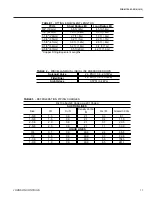
Page 11: ... 8m 1 9 ft 6m 2 2 ft 7m 2 6 ft 8m Solenoid Valve 2 3 PSI 13 8 20 7kPa Filter Drier 2 3 PSI 13 8 20 7kPa Sight Glass TABLE 2 MISCELLANEOUS LIQUID LINE PRESSURE DROPS 0 5PSI 3 4 kPa SUCTION LINES Size ID Cu ft Oz Ft Grams 30 Cm 1 3 8 1 3 0 0 2 1 0 3 8 1 1 5 8 1 5 0 0 2 1 0 4 11 5 2 1 8 2 0 0 0 2 1 0 7 20 0 2 5 8 2 5 0 0 2 1 1 1 30 9 LIQUID LINES 3 4 0 7 0 0 60 9 2 4 66 8 7 8 0 8 0 0 60 9 3 3 92 8 1 ...

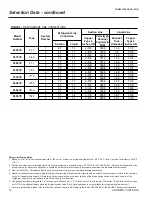
Page 12: ...ength 12 meters The field connections sizes are 7 8 for the optional factory mounted hot gas bypass valve Note Hot gas bypass is only available for refrigerant system number 1 7 For more information please refer to either the Johnson Controls DX Piping Guide Form 050 40 ES2 or the ASHRAE Refrigertion Handbook Tons Suction Line Liquid Line Suction Liquid 0248YE 81 3 1 2 7 1 1 2 5 8 1656 13 5 1 1 8 ...

Page 13: ...FORM 150 63 EG4 1012 13 JOHNSON CONTROLS INTENTIONALLY LEFT BLANK ...

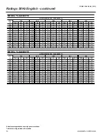
Page 14: ...1 61 6 12 1 67 0 65 2 11 2 64 8 69 1 10 2 41 0 75 6 55 6 14 6 73 6 58 7 13 5 71 5 62 1 12 5 69 3 65 8 11 5 67 0 69 7 10 5 43 0 78 1 56 1 14 9 76 0 59 3 13 8 73 9 62 7 12 8 71 6 66 3 11 8 69 3 70 3 10 8 45 0 80 7 56 8 15 2 78 5 59 9 14 2 76 3 63 2 13 1 74 0 66 9 12 1 71 6 70 8 11 1 47 0 83 3 57 4 15 6 81 1 60 5 14 5 78 8 63 9 13 4 76 5 67 5 12 4 74 0 71 5 11 4 49 0 86 0 58 1 15 9 83 7 61 1 14 8 81 ...

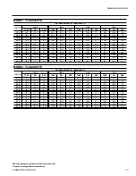
Page 15: ... 8 80 8 7 5 52 1 85 2 6 8 39 0 62 1 73 0 9 4 59 5 77 1 8 5 56 8 81 4 7 7 54 0 85 8 7 0 41 0 64 3 73 6 9 6 61 6 77 7 8 8 58 8 82 0 8 0 55 9 86 4 7 2 43 0 66 5 74 2 9 9 63 7 78 2 9 0 60 8 82 6 8 2 57 9 87 1 7 4 45 0 68 8 74 7 10 1 65 9 78 8 9 2 62 9 83 2 8 4 59 9 87 7 7 6 47 0 71 1 75 3 10 4 68 1 79 5 9 5 65 0 83 8 8 6 52 5 69 3 8 3 49 0 73 4 76 0 10 7 70 4 80 1 9 7 67 2 84 4 8 9 54 3 69 7 8 5 51 0 ...

Page 16: ...41 0 100 0 68 4 15 3 97 3 72 0 14 2 94 5 76 0 13 2 91 6 80 3 12 2 88 6 85 0 11 2 43 0 103 4 69 1 15 7 100 6 72 7 14 6 97 8 76 7 13 5 94 8 81 0 12 5 91 7 85 7 11 5 45 0 107 0 69 8 16 1 104 1 73 5 14 9 101 1 77 5 13 9 98 0 81 8 12 8 94 9 86 4 11 8 47 0 110 6 70 5 16 5 107 6 74 2 15 3 104 5 78 2 14 2 101 3 82 5 13 1 98 1 87 1 12 1 49 0 114 3 71 3 16 8 111 2 75 0 15 7 108 0 79 0 14 5 104 7 83 3 13 5 1...

Page 17: ...0 0 78 7 93 7 9 1 75 2 98 9 8 3 71 6 104 3 7 5 41 0 85 1 89 6 10 3 81 5 94 4 9 4 77 9 99 6 8 5 74 1 105 1 7 7 43 0 88 1 90 3 10 5 84 4 95 2 9 6 80 6 100 3 8 8 76 7 105 8 7 9 45 0 91 1 91 0 10 8 87 2 95 9 9 9 83 3 101 1 9 0 79 4 106 6 8 2 47 0 94 2 91 8 11 1 90 2 96 7 10 1 86 2 101 8 9 2 82 1 107 3 8 4 49 0 97 3 92 6 11 4 93 2 97 5 10 4 89 1 102 6 9 5 75 1 89 7 9 0 51 0 100 5 93 4 11 7 96 3 98 3 10...

Page 18: ... 159 0 98 2 17 1 154 5 103 1 15 9 149 9 108 3 14 8 145 2 113 9 13 7 140 4 119 9 12 6 55 0 164 1 99 4 17 4 159 4 104 3 16 2 154 6 109 6 15 1 149 8 115 2 14 0 144 8 121 2 12 9 MODEL YLUA0498YE AIR TEMPERATURE ON CONDENSER F 75 0 80 0 85 0 90 0 95 0 TONS KW EER TONS KW EER TONS KW EER TONS KW EER TONS KW EER 35 0 128 5 100 7 13 5 124 9 106 0 12 5 121 2 111 9 11 6 117 4 118 2 10 7 113 5 124 9 9 8 37 0...

Page 19: ...19 3 137 8 9 5 93 1 104 9 9 4 53 0 134 7 125 9 11 6 128 9 132 3 10 6 123 1 139 0 9 7 96 2 105 7 9 7 55 0 139 0 127 2 11 9 133 0 133 6 10 9 126 9 140 3 9 9 99 4 106 5 9 9 MODEL YLUA0498YE AIR TEMPERATURE ON CONDENSER F LCWT F 100 0 105 0 110 0 115 0 TONS KW EER TONS KW EER TONS KW EER TONS KW EER 35 0 108 8 131 7 9 0 104 1 138 9 8 2 99 3 146 6 7 4 94 3 154 8 6 7 37 0 112 7 132 8 9 3 107 8 140 0 8 4...

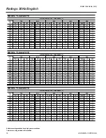
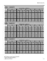
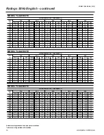
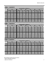
Page 20: ... 249 8 62 8 3 6 235 7 69 7 3 1 218 5 76 8 2 6 200 7 84 6 2 2 6 0 270 9 57 3 4 2 257 4 63 3 3 7 242 9 70 2 3 2 225 3 77 4 2 7 207 0 85 2 2 3 7 0 279 0 57 8 4 3 265 1 63 8 3 8 250 3 70 7 3 2 232 2 77 9 2 7 213 5 85 7 2 3 8 0 287 2 58 4 4 4 273 0 64 4 3 8 257 8 71 3 3 3 239 2 78 4 2 8 220 0 86 3 2 4 9 0 295 6 59 0 4 5 281 0 64 9 3 9 265 4 71 8 3 4 246 4 79 0 2 9 226 7 86 9 2 4 10 0 304 0 59 6 4 6 289...

Page 21: ... 3 289 2 93 4 2 8 265 9 102 8 2 4 6 0 358 6 70 4 4 5 340 5 77 5 3 9 321 5 85 6 3 4 298 3 94 1 2 9 274 3 103 5 2 4 7 0 369 7 71 1 4 6 351 1 78 1 4 0 331 4 86 2 3 4 307 5 94 8 2 9 282 8 104 2 2 5 8 0 380 9 71 8 4 7 361 7 78 8 4 1 341 4 86 9 3 5 316 9 95 4 3 0 291 5 104 9 2 5 9 0 392 4 72 4 4 8 372 6 79 5 4 2 351 7 87 6 3 6 326 4 96 1 3 1 300 3 105 6 2 6 10 0 404 1 73 2 4 9 383 7 80 2 4 3 362 2 88 3 ...

Page 22: ... 103 0 2 9 12 0 558 1 100 5 4 9 528 8 109 7 4 3 498 3 120 3 3 7 461 8 131 3 3 2 348 4 103 7 3 0 MODEL YLUA0498YE AIR TEMPERATURE ON CONDENSER C 25 0 30 0 35 0 40 0 45 0 KW KW COP KW KW COP KW KW COP KW KW COP KW KW COP 2 0 451 7 103 0 3 9 428 2 113 4 3 4 403 3 125 2 2 9 373 4 137 7 2 5 342 3 151 8 2 1 3 0 466 1 104 0 4 0 441 9 114 4 3 5 416 2 126 2 3 0 385 4 138 7 2 5 353 4 152 7 2 1 4 0 480 9 105...

Page 23: ...V 16 3 EER FULL LOAD DISPL COMPR KW AMBIENT F FULL LOAD DISPL COMPR KW AMBIENT F FULL LOAD DISPL COMPR KW AMBIENT F FULL LOAD DISPL COMPR KW AMBIENT F YLUA0338YE TONS UNIT EER 100 0 113 0 75 4 80 0 15 9 86 1 99 0 63 5 80 0 16 1 57 0 66 4 39 4 80 0 16 1 43 0 49 1 30 6 80 0 16 6 13 9 15 5 9 6 80 0 16 5 IPLV 16 4 EER YLUA0408YE TONS UNIT EER 100 0 133 0 94 9 80 0 15 2 75 0 101 7 68 0 80 0 15 6 50 0 7...

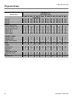
Page 24: ...il Charge ckt1 l 9 8 12 4 12 4 10 4 12 4 12 6 18 9 18 9 Oil Charge ckt2 l 9 8 9 8 10 4 10 4 12 6 12 6 10 4 12 6 Shipping Weight kg 1684 2 1809 4 1898 3 2227 6 2334 2 2368 2 2936 1 3006 4 Compressors scroll type Compressors per circuit 3 3 3 3 3 2 2 2 3 2 2 2 3 2 3 2 Compressors per unit 6 6 5 4 5 4 5 5 Nominal Tons per compressor Circuit 1 45 7 52 7 52 7 52 7 112 5 52 7 112 5 112 5 112 5 Circuit 2...

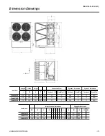
Page 25: ...7 84 3 YLAA0278YE 116 1 88 3 95 3 89 7 43 9 2 7 1 1 39 6 17 17 84 3 YLAA0298YE 116 1 88 3 95 3 89 7 43 9 2 7 1 1 39 6 17 17 84 3 System 1 Dimensions System 2 Dimensions New Model Isolator Location Dimensions Rigging Hole Locations D2 I1 I2 I3 I4 I5 I6 I7 I8 A B R1 R2 R3 R4 YLAA0248YE 35 5 19 5 76 6 1 3 85 5 23 2 68 3 YLAA0278YE 35 5 19 5 76 6 1 3 85 5 23 2 68 3 YLAA0298YE 35 5 18 5 76 6 1 3 85 5 2...

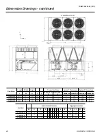
Page 26: ...9 2 7 1 1 41 17 1 26 9 84 4 YLUA0408YE 143 5 88 3 95 3 89 7 43 9 2 7 1 1 41 26 9 26 9 84 4 System 1 Dimensions System 2 Dimensions Suction In 1 2 Liquid Out 1 2 New Model Isolator Location Dimensions Rigging Hole Locations D2 I1 I2 I3 I4 I5 I6 I7 I8 A B R1 R2 R3 R4 YLAA0308YE 35 5 7 6 117 2 1 4 85 5 23 2 95 9 YLAA0338YE 35 5 7 6 117 2 1 4 85 5 23 2 95 9 YLAA0408YE 35 5 7 6 117 2 1 4 85 5 23 2 95 9...

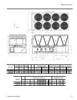
Page 27: ...3 9 3 1 2 7 1 4 1 1 41 4 26 5 111 3 44 7 YLUA0498YE 187 5 88 3 95 3 89 7 43 9 3 1 2 7 1 4 1 1 41 4 26 5 111 3 44 7 System 1 Dimensions System 2 Dimensions Suction In 1 2 Liquid Out 1 2 New Model Isolator Location Dimensions Rigging Hole Locations D2 I1 I2 I3 I4 I5 I6 I7 I8 A B R1 R2 R3 R4 YLAA0468YE 35 5 7 6 69 80 1 4 85 5 39 66 58 YLAA0498YE 35 5 7 6 69 80 1 4 85 5 39 66 58 ...

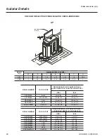
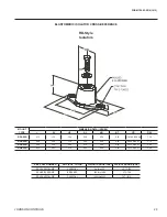
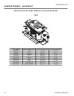
Page 28: ...900 DARK GREEN 435 thru 765 198 thru 347 CP 1D 1200 GRAY 766 thru 1020 348 thru 463 CP 1D 1360 WHITE 1021 thru 1156 464 thru 524 CP 1D 1785N GRAY RED 1157 thru 1785 525 thru 810 MODEL NUMBER COLOR CODE RATED CAPACITY FOR UNITS WITH ANY LOAD POINT ABOVE 1518 LBS 689 KG LBS KG C2P 1D 1350 DARK PURPLE Up thru 1148 Up to 521 C2P 1D 1350 DARK PURPLE Up thru 1148 Up to 521 C2P 1D 1800 DARK GREEN 1149 th...

Page 29: ...1 75 3 00 0 34 0 22 3 8 16 UNC X 1 1 75 RD3 WR 5 50 3 38 2 88 4 13 0 56 0 25 1 2 13 UNC X 1 2 50 RD4 WR 6 25 4 63 2 75 5 00 0 56 0 38 1 2 13 UNC X 1 3 00 VMC PART NUMBER VMC ISOL COLOR WEIGHT RANGE LBS WEIGHT RANGE KGS RD 3 CHARCOAL WR CHARCOAL Up thru 825 UP TO 374 RD 4 BRICK RED WR BRICK RED 826 thru 1688 375 766 RD 4 CHARCOAL WR CHARCOAL 1689 thru 4000 767 1814 ELASTOMERIC ISOLATOR CROSS REFERE...

Page 30: ...GE KGS Y2RSI 2D 460 GREEN Up thru 391 UP TO 177 Y2RSI 2D 460 GREEN Up thru 391 UP TO 177 Y2RSI 2D 710 DARK BROWN 392 thru 604 178 274 Y2RSI 2D 870 RED 605 thru 740 275 336 Y2RSI 2D 1200N RED BLACK 741 thru 1020 337 463 Y2RSI 2D 1690 PINK 1021 thru 1437 464 652 Y2RSI 2D 2640N PINK GRAY 1438 thru 2244 653 1018 Y2RSI 2D 2870N PINK GRAY ORANGE 2245 thru 2618 1019 1188 Y2RSI 2D 3280N PINK GRAY DK BROWN...

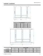
Page 31: ...ns AVM LOCATIONS YLUA MODEL I1 I2 A B YLU A0248YE 19 5 76 6 1 36 85 5 YLU A0278YE 19 5 76 6 1 36 85 5 YLU A0298YE 19 5 76 6 1 36 85 5 YLUA MODEL AVM LOCATIONS I1 I2 A B YLUA0308YE 7 6 117 2 1 4 85 5 YLUA0338YE 7 6 117 2 1 4 85 5 YLUA0408YE 7 6 117 2 1 4 85 5 ...

Page 32: ...32 JOHNSON CONTROLS FORM 150 63 EG4 1012 YLUA MODEL AVM LOCATIONS I1 I2 I3 A B YLUA0468YE 7 6 69 0 80 0 1 4 85 5 YLUA0498YE 7 6 69 0 80 0 1 4 85 5 Isolator Locations continued ...

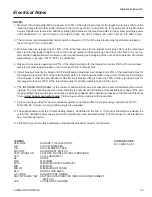
Page 33: ...tures in excess of 95ºF 35ºC is anticipated 4 Maximum fuse size is based upon 225 of the rated load amps for the largest motor plus 100 of the rated load amps for all other loads included in the circuit per N E C Article 440 22 5 Circuit breakers must be UL listed and CSA certified and maximum size is based on 225 of the rated load amps for the largest motor plus 100 of the rated load amps for all...

Page 34: ...25 250 105 150 125 150 105 150 125 150 0338 50 222 250 250 250 90 100 100 110 139 150 175 175 0408 50 256 400 300 300 135 150 150 175 135 150 150 175 0468 50 289 400 350 350 193 250 225 225 109 150 125 150 0498 50 318 400 350 350 193 250 225 225 139 150 175 175 CHILLER MODEL VOLT CODE MIN N F DS MIN DUAL ELEM FUSE MIN CB MAX DUAL ELEM FUSE MAX CB MINIMUM CIRCUIT AMPS MIN N F DISC SW MIN DUAL ELEM ...

Page 35: ...4 19 0 0278 50 25 198 25 198 25 198 2 4 19 0 22 140 22 140 22 140 2 4 19 0 0298 50 25 198 25 198 25 198 2 4 19 0 55 310 25 198 2 4 19 0 0308 50 25 310 25 198 3 4 19 0 55 310 25 198 3 4 19 0 0338 50 25 198 25 198 25 198 2 4 19 0 55 310 55 310 4 4 19 0 0408 50 55 310 55 310 3 4 19 0 55 310 55 310 3 4 19 0 0468 50 55 310 55 310 55 310 4 4 19 0 55 310 25 198 4 4 19 0 0498 50 55 310 55 310 55 310 4 4 1...

Page 36: ...36 JOHNSON CONTROLS FORM 150 63 EG4 1012 Electrical Drawings ...

Page 37: ...FORM 150 63 EG4 1012 37 JOHNSON CONTROLS ...

Page 38: ...38 JOHNSON CONTROLS FORM 150 63 EG4 1012 Electrical Drawings continued ...

Page 39: ...FORM 150 63 EG4 1012 39 JOHNSON CONTROLS ...

Page 40: ...40 JOHNSON CONTROLS FORM 150 63 EG4 1012 Electrical Drawings continued ...

Page 41: ...FORM 150 63 EG4 1012 41 JOHNSON CONTROLS ...

Page 42: ...42 JOHNSON CONTROLS FORM 150 63 EG4 1012 Electrical Drawings continued ...

Page 43: ...FORM 150 63 EG4 1012 43 JOHNSON CONTROLS ...

Page 44: ... YORK KP PUMP CONTACTOR PART INCLUDING COIL SUPPRESSOR ITEMS THUS ENCLOSED FORM A KT RELAY TIMER COMPONENTS OR SETS OFCOMPONENTS M COMPRESSOR MOTOR MF MOTOR FAN MP MOTOR PUMP NU NOT USED PE PROTECTIVE EARTH PWM PULSE WIDTH MODULATION TEMP RESET or REMOTE UNLOAD 2nd STEP YLLSV FSI NB GENERAL a THIS DRAWING IS BASED ON IEC SYMBOLS b FIELD WIRING TO BE IN ACCORDANCE WITH THE RELEVANT ELECTRICAL CODE ...

Page 45: ... 6 FANS 16 INPUT SWITCH DISCONNECT STANDARD ON CE UNITS OR CIRCUIT BREAKER OPTION REPLACES INPUT TERMINAL BLOCK 17 INPUT SWITCH DISCONNECT INDIVIDUAL SYSTEM CIRCUIT BREAKER OPTION REPLACES INPUT TERMINAL BLOCK 18 115V CONTROL CIRCUIT REQUIRES A 115V SUPPLY UNLESS CONTROL CIRCUIT TRANSFORMER T2 F3 ARE FITTED STANDARD ON CE UNITS 19 FOR OPTIONAL HYDRO KIT HEATER EPH IS FITTED AND WIRED AS SHOWN ON S...

Page 46: ... the units be installed on a substantial base that will not settle caus ing strain on the refrigerant lines and resulting in possible leaks A one piece concrete slab with footers extending below the frost line is highly recommended particularly in areas where winters are long and very cold Additionally the slab should not be tied to the main build ing foundation as noises will telegraph Mounting h...

Page 47: ...mmission as shown on the schedules and plans factory assembled charged and tested air cooled scroll compressor condensing unit as specified herein Condensing Unit shall be de signed selected and constructed using a refrigerant with Flammability rating of 1 as defined by ANSI ASHRAE STANDARD 34 Number Designation and Safety Classification of Refrigerants Condensing Unit shall include but is not lim...

Page 48: ...le Set points within Manufacturer limits display language suction pressure set ting and control range remote reset temperature range set daily schedule holiday for start stop manual override for servicing low and high ambient cutouts number of compressors low suction pressure cutout high discharge pressure cutout anti recycle timer compressor start cycle time and anticoincident timer delay compres...

Page 49: ...power voltage for servicing Factory interconnecting wiring from disconnect to factory supplied circuit breakers 4 Single Point Circuit Breaker Single point Ter minal Block with Circuit Breaker and lockable external handle in compliance withArticle 44014 of N E C can be supplied to isolate power volt age for servicing Incoming power wiring must comply with the National Electric Code and or local co...

Page 50: ...C input to reset the discharge air temperature O Sound Reduction Factory Mounted 1 Low speed reduced noise fans 2 Compressor Acoustic Sound Blankets P Vibration Isolation Field Mounted 1 Neoprene Pad Isolators 2 1 Inch Deflection Spring Isolators Level adjust able spring and cage type isolators for mounting under the unit base rails 3 2 Inch Deflection Isolators Level adjustable re strained mounts...

Page 51: ...FORM 150 63 EG4 1012 51 JOHNSON CONTROLS ...
Page 52: ...www johnsoncontrols com 2012 Johnson Controls Inc Printed on recycled paper Form 150 63 EG4 1012 Supersedes 150 63 EG4 1009 ...

Reviews: