JOHNSON CONTROLS
36
FORM 160.81-NOM1
ISSUE DATE: 10/3/2020
SECTION 1 – INSTALLATION
CONDENSER
SHELL
CODE
C
DUAL RELIEF VALVE
1
CR
OUTLET
LBS. AIR PER
MIN. (kPa)
NPT
T
42.1 (290.3) 55.9 (385.4)
1-11-1/2 (FEM)
V
53.8 (370.9) 55.9 (385.4)
1-11-1/2 (FEM)
W
59.4 (409.5) 91.8 (632.9) 1-1/4 - 11-1/2 (FEM)
X
73.3 (505.4) 91.8 (632.9) 1-1/4 - 11-1/2 (FEM)
NOTES:
1. Dual relief valve consists of one three-way shut-off valve and two single relief valves. The valve configuration will not allow both valves
to be shut off at the same time, and valves are sized such that each relief valve has sufficient discharge capacity when used alone. This
permits safe removal of either relief valve for repair or replacement, while maintaining vessel protection.
2. ASHRAE 15-1994 Section 9.8 and Appendix F describes relief requirements for positive dis placement compressors. Summarized, the unit
must be equipped with a relief device suitable for relieving the entire compressor capacity.
Where:
Cr = Rated capacity of YORK supplied relief valve at
235 PSIG.
Relief valve set pressure - 235 PSIG (1,621 kPa).
UNIT PIPING
Compressor lubricant piping and system refrigerant
piping are factory installed on all units shipped assem-
bled. On units shipped dismantled, the following pip-
ing should be completed under the supervision of the
Johnson Controls Representative; the lubricant piping;
system oil return using material furnished.
CONTROL WIRING
After installation of the control center on units shipped
disassembled, the control wiring must be completed
between unit components and control center or solid
state starter when used, using the wiring harness fur-
nished.
Field wiring connections for commonly encountered
control modifications (by others), if required, are
shown on
Wiring Diagram (Form 160.81‑PW5)
.
No deviations in unit wiring from that
shown on drawings furnished shall be
made without prior approval of the John-
son Controls Representative.
POWER WIRING
Unit With Electro-Mechanical Starter
A 115 volt – single-phase – 60 or 50 Hertz power sup-
ply of 15 amperes must be furnished to the control cen-
ter, from the control transformer (1-1/2 kVa required)
included with the compressor-motor starter. DO NOT
make final power connections to control center until
approved by Johnson Controls Representative. Refer
to
Wiring Diagram (Form 160.81‑PW3)
,
Power Wir‑
ing.
Johnson Controls recommends that all connec-
tions to the unit be flexible. Consult with and conform
to all local regulatory requirements.
Remote Electro-Mechanical Starters for
the YR Unit must be furnished in accor-
dance with YORK Standard.
Each YR unit is furnished for a specific electrical pow-
er supply as stamped on the unit data plate, which also
details the motor connection diagrams.
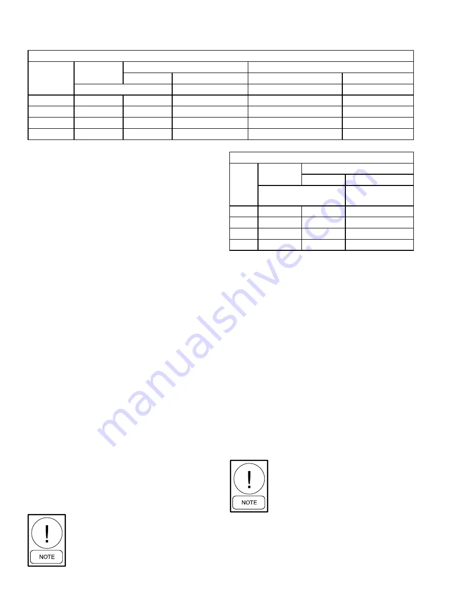
TABLE 11 -
REFRIGERANT RELIEF CHARACTERISTICS
EVAPORATOR
SHELL
CODE
C
SINGLE RELIEF VALVE
DUAL RELIEF VALVE
1
CR
OUTLET
CR
OUTLET
LBS. AIR PER MIN. (kPa)
NPT
LBS. AIR PER MIN. (kPa)
NPT
T
34.7 (239.3)
55.9 (385.4)
1-11-1/2 (FEM)
55.9 (385.4)
1-11-1/2 (FEM)
V
48.5 (334.4)
55.9 (385.4)
1-11-1/2 (FEM)
55.9 (385.4)
1-11-1/2 (FEM)
W
48.0 (330.9)
91.8 (632.9)
1-1/4 - 11-1/2 (FEM)
91.8 (632.9)
1-1/4 - 11-1/2 (FEM)
X
64.0 (441.3)
91.8 (632.9)
1-1/4 - 11-1/2 (FEM)
91.8 (632.9)
1-1/4 - 11-1/2 (FEM)


