JOHNSON CONTROLS
43
SECTION 2 - OPTIVIEW CONTROL CENTER INTRODUCTION
FORM 160.67-O1
ISSUE DATE: 4/1/2015
2
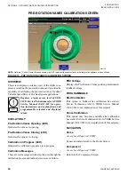
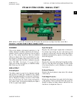
STeaM SYSTeM SCreen - Manual STarT
LD09259
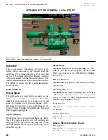
figure 16 - STeaM SYSTeM SCreen - Manual STarT
noTe:
OptiView™ Control Center Screens shown may NOT represent the exact screens according to the software version utilized.
overvieW
This screen displays information pertaining to the
turbine and steam condenser and shows all steam pa-
rameters and the status of turbine and steam control
devices. The cooling liquid flow lines are animated
whenever adequate flow has been established to close
the refrigerant condenser liquid flow switch contacts.
The turbine steam inlet flow line is animated at speeds
above 500 RPM. See
Figure 17 on page 46
for a
typical screen that would appear if a MSSP4-Turbine
Start Mode is set for AUTO.
diSplaY onlY
Turbine Speed
The turbine speed is sensed by two magnetic pickups
that monitor a toothed gear installed on the turbine
shaft. The pickup signals are converted to 4-20 mA sig-
nals by frequency-to-analog converters in the Turbine
Box and connected to the Frick Analog I/O Board in
the Control Center. This data field displays the highest
of the two speed input signals.
Speed Setpoint
Displays the current speed setpoint that is dictated by
the startup logic during the slow roll warm-up and
ramp up to rated speed. After the chiller has attained
minimum rated speed, the capacity control logic deter-
mines this setpoint.
Steam flow
Displays the rate of steam flowing through the turbine.
This text and data field only appears if FSE1-Steam
Flow Sensor Enable is set for Enabled on Configura-
tion Screen 2.
exhaust pressure
Displays the steam pressure measured at the exhaust
of the turbine.
first Stage pressure
Displays the steam pressure measured in the first stage
of the turbine. This text and data field only appears if
MSSP15-Turbine First Stage Pressure Sensor is set for
Enabled on Configuration Screen 1.
Summary of Contents for YST
Page 163: ...JOHNSON CONTROLS 163 NOTES...


