• Installation requires a bolting or anchoring mount to support the structure with a
minimum two 5/8 in. (15.88 mm) diameter bolt or two 1/2 in. (12.7 mm) diameter concrete
anchors.
• All springs are designed for 50% over-travel.
• See
Installing optional spring isolators
for installation instructions.
• Isolators with 1 in. (25.4 mm) deflection must be of the same class for the entire unit. That
is, C2Ps must be used at all locations on a selected unit, or all CPs.
• Pin 63 is for isolators, X = no isolators only active selection, 1 = 1 in. (25.4 mm) deflection
not active, N = neoprene not active.
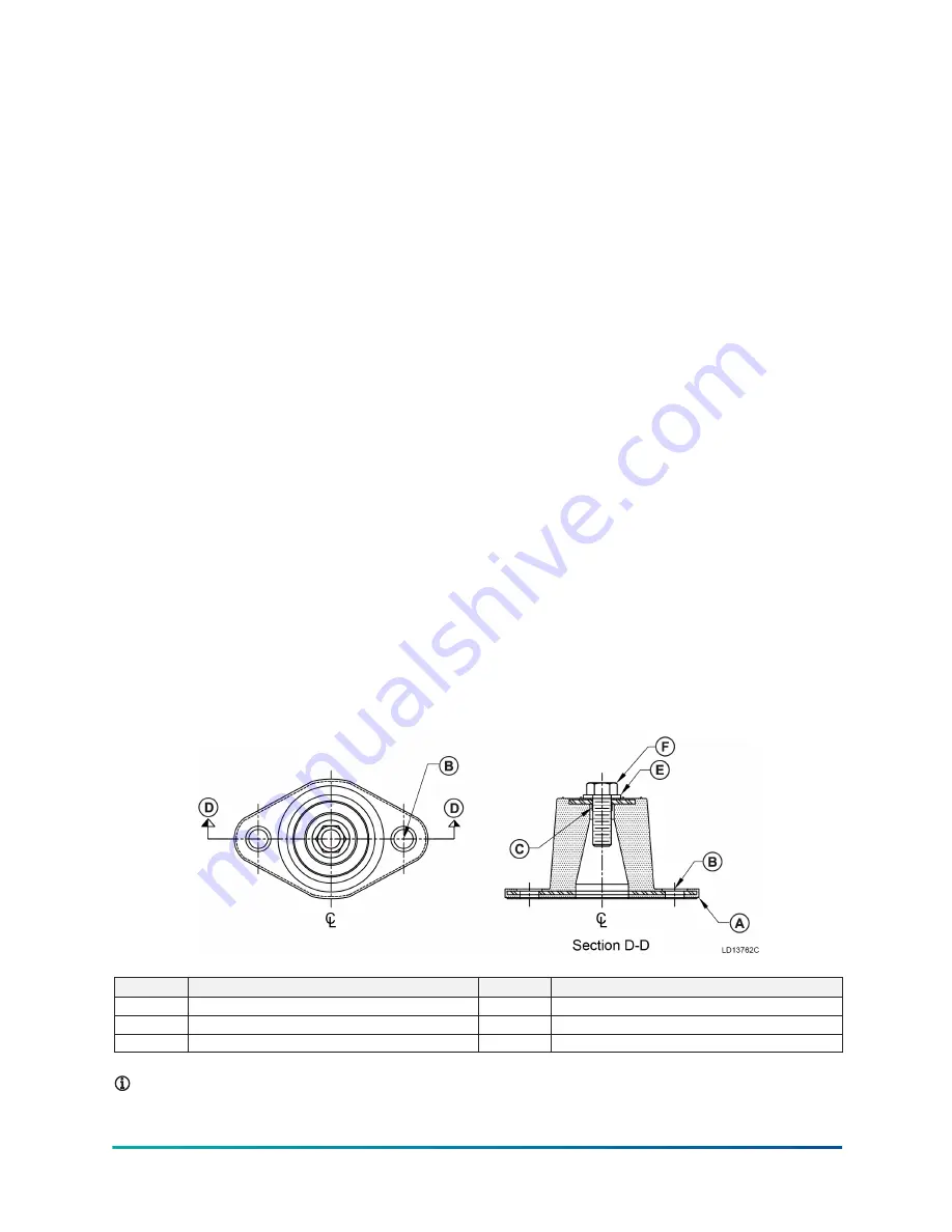
Installing optional elastomeric isolators
If ordered, elastomeric type isolator assemblies are supplied with the unit. The isolator load rating
can vary based on the location on the chiller. This is due to the weight distribution of the unit and
the isolators must be located as prescribed in the technical data portion of the chiller submittal
package. See
Figure 32
for locations on units with 20 fans and
Figure 33
for locations on units with
26 fans. See
Table 11
for isolator details.
Spring isolators are shipped fully assembled and must be positioned in accordance with the
submittal drawings or as otherwise recommended.
1. Set the isolators on the floor, housekeeping pad, or subbase, and ensure that all isolator
centerlines match the equipment mounting holes.
2. VMC Group recommends that the isolator base (A) be installed on a level surface. Shim or grout
as required, leveling all isolator bases to the same elevation. The maximum difference that can
be tolerated is 1/32 in. (0.794 mm).
3. Bolt or anchor all isolators to supporting structure using base slotted holes (B).
4. Remove the top bolt and washer.
5. Place the equipment on top of the isolators, making sure that the mounting holes of the
equipment line up with the isolator threaded hole (C).
6. To complete the installation, reinstall the top bolt and washer and tighten.
Figure 36: Elastomeric isolator details
Callout
Description
Callout
Description
A
Isolator base
D
Cross section points
B
Base slotted holes
E
Top washer
C
Isolator threaded hole
F
Top bolt
Note:
Isolators are square or rectangular.
YVAM Air-Cooled Centrifugal Liquid Chiller
32


