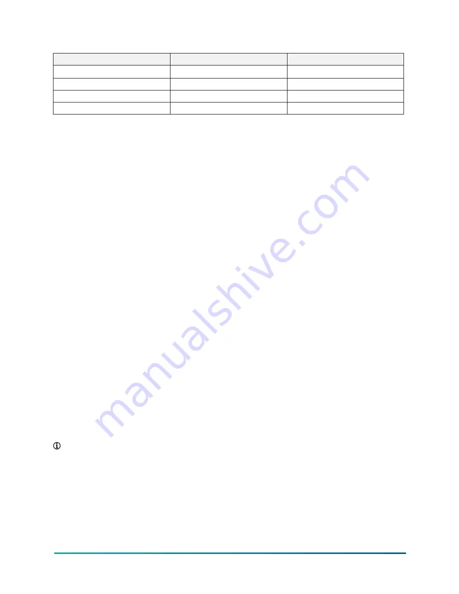
Table 13: Chemical consideration of water
Water content
Concentration
Time limit (analyze before)
Nitrate (NO
3
-
)
˂ 100 ppm
No limit
Iron (Fe)
˂ 0.2 mg/l
No limit
Aluminum (Al)
˂ 0.2 mg/l
No limit
Manganese (Mn)
˂ 0.1 mg/l
No limit
Variable primary flow
For variable primary flow applications, Johnson Controls recommends a maximum 10% per minute
flow rate of change, based on design flow.
Provide 8 gal to 10 gal per chiller ton (8.6 l to 10.8 l per cooling kW) system water volume.
Insufficient system volume and rapid flow changes can cause control problems or can even cause
chiller shutdowns. There are many other design issues to evaluate with variable primary flow
systems. Consult your Johnson Controls sales office for more information about successfully
applying YVAM chillers.
Check for piping alignment
When the piping is completed, open a connection in each line as close to the unit as possible by
removing the flange bolts or coupling and check for piping alignment. If any of the bolts are bound
in their holes, or if the connection springs are out of alignment, correct the misalignment.
After the connections are made and the alignment verified, fill the unit with water to check for
leaks.
If spring isolators are installed, perform final adjustments to the leveling bolts until the wedges
and shims can be removed. Check that the unit is in the correct level position, clear of the floor or
foundation, and without any effect from the weight of the piping.
Permanent strainers
Permanent strainers are required in the evaporator water circuit to protect the chiller and the
pumps, the chilled water air handler coils and controls, and similar components. Johnson Controls
do not provide the permanent strainers. The strainer must be installed in the entering water circuit
upstream and near to the chiller.
Water piping must be arranged to prevent water voids from entering the chiller, and be controlled
as required to avoid rapid flow transients.
If the pumping arrangement is set up to discharge into the chiller, the strainer can be located
upstream of the pumps to protect both the chiller and the pumps. For this type of arrangement, the
piping between the pump and chiller must be thoroughly cleaned before chiller start up.
If the pumps and chillers are remote from each other, the strainers must be located directly
upstream of the chiller as described previously.
Note:
The evaporator must be protected by a strainer, preferably made of 16 mesh. The
strainer must be fitted as close as possible to the liquid inlet connection, with a means of local
isolation.
Stop valves
Stop valves can be provided in the evaporator water piping adjacent to the chiller to facilitate chiller
maintenance. Johnson Controls do not provide the stop valves. To monitor chiller operation, install
site thermometer wells and pressure taps in the piping as close to the chiller as possible.
37
YVAM Air-Cooled Centrifugal Liquid Chiller


