background image

Printed In CANADA

DOC-YS-Green-00-1v0PR02 • July 14, 2014

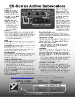
Input Mode

Line Level

 - Use when fed 

a signal directly from a line 

level output. It’s recommended 

to use balanced cables with 

XLR connectors or TRS ¼-inch 

phone plugs (Tip, Ring, Sleeve) 

to help reduce the unit’s 

sensitivity to hum and buzz.

Speaker Level

 - Set to 

speaker level when fed from 

an amplifier or speaker out 

from a ‘powered’ mixer! 

WARNING: Do not plug 

in two speaker level 

sources to a single ES 

Powered Subwoofer! 

Sub Level

Adjusts the bass added to the sound system by the ES Powered Sub. 

It’s recommended to set the control while operating at a low sound 

level. A ‘12 o’clock’ setting on the ES Series Powered Subwoofer’s Level 

control is the correct starting point when setting up a sound system. 

Note: At high output levels, this control may be 

overridden by the internal limiter.

Mode

Punch Mode

 processes the sound so it’s perceived as 

punchier, giving less power into deep bass and more 

into the upper bass.

Smooth Mode

 will keep the original signal character with no 

preference for deep or upper bass.

Deep mode

 processes the signal with a deeper sound, 

giving more power into deep bass while keeping the 

upper bass similar to the Smooth Mode. 

Hi Freq. Rolloff

Sets the upper bass frequency which the ES Powered Sub rolls off, 

providing part of the ‘crossover’ function. Ideally the ES Powered 

Sub would be used with an élite powered top cabinet (both 

cabinets set at 100 Hz).

Input / Output LINK Jacks

All Link jacks are connected in parallel, use them to daisy-chain other 

ES Powered Subs or full-range enclosures. For normal operation, 

connect the ES Series Powered Subwoofer just like an ordinary 

speaker along with the full range enclosures. 

Note: the Mono Blend Input is designed for Line 

Level signals only! 

Line Level - 

If receiving the signal from a 

non-powered


mixer, a line level signal processor or another line-level source, 

set the input switch to Line.

Speaker Level

 - Set the Input Level switch to Speaker if the 

signal is coming directly from a power amplifier, ‘powered’ mixer, or 

another powered source.

Note: The ES Powered 

Sub can be plugged in 

before or after the full 

range enclosure, it does 

not alter the signal to the 

daisy chained enclosures. 

An external crossover is 

not necessary.
Tip: The Link jacks allow 

many ES Series Powered 

Subs to be connected in a 

string (parallel). There is no 

practical limit to the number 

of ES Powered Subs that 

may be connected together.
WARNING: Do not plug in 

two speaker level sources to 

a single ES Powered Sub

Mono Blend Input Jack

This input jack enables you to connect a secondary line level signal 

without needing to externally sum two signals (e.g. Left and Right). This is 

helpful when you are adding a single ES Powered Sub to a stereo system.  

Bluetooth™ Control

This control enables or disables the Bluetooth™ connection between 

a tablet or a smart phone using the Yorkville App. Pressing the 

Bluetooth™ button for more than 4 seconds resets the ES-Series 

powered subwoofer to factory settings.

Note: The Bluetooth

 functionality on this product 

is intended for control only.  It does not allow for 

Bluetooth

 audio connection

Protection

The ES Series Powered Subs use a DSP-based circuit to prevent 

clipping, over power and over excursion. At high levels, the limiter will 

limit the gain. The level control should be set while operating at low 

levels. Turn the master volume of the signal going to the subwoofer 

down to allow the balancing and setting of the bass along with the full 

range speaker top in use.  

Note: At high power levels, when the limiter is operating, 

increasing the Subwoofer’s Level Control will NOT 

increase the output.. Do NOT continue to increase this 

setting while operating at high levels. 

Stand Mounting Adapter

The ES Series Powered Subs come equipped with a built-in stand 

mounting adapter that can be used with Yorkville SW-Teletube accessory 

to support élite powered top cabinets. The support tube can be adjusted 

up to its full 5-foot 4-inch extension safely as long as the ES Series 

Powered Subwoofer is not inclined more than 10° (10-degrees).

WARNING: Larger or heavier cabinets should not be used! 

Do not use larger than the recommended top cabinets! 

ES-Series Active Subwoofers

TEMP

X-MAX

ACTIVITY

CLIP

LIMIT

POWER

MONO BLEND INPUT

1

2

3

MODE

HI FREQ.

ROLLOFF

INPUT

MODE

LINE

SPKR

INPUT

OUTPUT

SUB

LEVEL

12

dB

1.

2.

3.

Punchy

Smooth

Deep

Hz

WIRELESS

CONTROL

Bluetooth

TM

SMART

150

80

130

90

120

110

LED Flashing:

Ready to Connect
LED On:

Connected

Enable / Disable
Hold 4 sec. to reset

*

 Controls may not reflect

the applied settings if Bluetooth 

remote function is enabled.

*

*

*

Recommended for

élite speaker cabinets.

Line Level Sources Only!

0

NOTE:  THE YORKVILLE APP IS NEEDED TO CONTROL FUNCTIONS

THROUGH BLUETOOTH

TM

 AND IS NOT FOR  STREAMING AUDIO!  

Printed In CANADA

QuickStart-ES_P-00-1v4 • YS#QSTART-ESP) • January 22, 2020

To get the full Owner’s Manual please visit our website at 

http://www.yorkville.com/manuals/


or, if you need a printed version call 

905-837-8777

Summary of Contents for ES12P

Page 1: ...cing SMT components requires expensive specialized de soldering equipment and training Yorkville Sound will repair and replace defective SMT components to ensure proper quality assurance and installat...

Page 2: ...se la masse dispose de deux lames en plus d une troisi me tige qui connecte la masse La lame plus large ou la tige de mise la masse est pr vu pour votre s curit La prise murale est d su te si elle n e...

Page 3: ...N INPUT Switch set to LINE MIXER ES12P STEREO PASSIVE SPEAKER CONFIG INPUT Switch set to SPKR PWR AMP ES12P 1 ES12P 2 INPUT Switch set to LINE MIXER STEREO ACTIVE SPEAKER CONFIGURATION ES12P 1 ES12P 2...

Page 4: ...XLR Link Output 1 x XLR Link Output 1 x XLR Link Output Level Controls Master Sub Level Master Sub Level Master Master Sub Level LED Indicators Power Activity Protection Clip X Max Temp Power Activity...

Page 5: ...XLR Sortie Link 1 x XLR Sortie Link 1 x XLR Sortie Link Commandes de Niveau Principale Niveau du Subwoofer Master Sub Level Principale Principale Indicateurs DEL Alimentation Activit Protection Clip X...

Page 6: ...A C T U R E D B Y Y O R K V I L L E S O U N D MONO BLEND INPUT 1 3 2 1 3 2 2 3 1 SUB LEVEL LINE SPKR Mode DSP HF ROLLOFF 170 80 NOTES ALL LINK CONNECTIONS FUNCTION AS INPUTS OR OUTPUTS MONO BLEND INP...

Page 7: ...IRGP50B60PD1PBF T0247 NPN IGBT T ZD200 7832 MM3Z18VT1G 18V0 0W2 5 SMT ZEN C231 5979 100N 50V 5 CAP 0805 SMT X7R Q204 8165 MMBTA92 PNP SOT 23 SMT C232 7917 _33U 25V 20 CAP 6 3X5 5 SMT EL Q205 2496 IRG...

Page 8: ...X7R R40 7745 W125 0R 5 0805 SMT RES C37 8178 470P 250V 5 CAP 0603 SMT NP0 R42 7899 W125 1K800 0 1 0805 SMT RES C38 5979 100N 50V 5 CAP 0805 SMT X7R R44 7860 W125 4K7 5 0805 SMT RES C39 5979 100N 50V 5...

Page 9: ..._1U 25V 20 CAP 1206 SMT X7R L401 2906 486UH COIL COMMON MODE 8A SMT U207 8211 LNK302G OFFLINE SWITCH SMT SMD8B C238 7735 __4U7 50V 10 CAP 1210 SMT CER PCB1 M1823BLANK 2_OZ 2SD 89 81SQIN 1PER ES PSA2S...

Page 10: ...0MM C309 MURS120T3 DO214AA D306 MURS120T3 DO214AA D307 MURS120T3 DO214AA D302 100V 100N 1206 C306 TO POWER AMP PCB 250V 100N X2 18MM C302 250V 680N X2 30MM C305 MURS120T3 DO214AA D305 1 2 3 4 6 5 POWE...

Page 11: ...00 PIC20201 PIC20202 COC202 PIC20301 PIC20302 COC203 PIC20401 PIC20402 COC204 PIC20501 PIC20502 COC205 PIC20601 PIC20602 COC206 PIC20701 PIC20702 COC207 PIC20801 PIC20802 COC208 PIC20901 PIC20902 COC2...

Page 12: ...and pin 4 of U201 For M1693 PCB Only Change Q203A and Q205A from IRGP50B60PDPbF YS 2385 to IRGP50B60PD1PbF YS 2496 For M1692 PCB Only Change Q203A and Q205A from IRGP50B60PDPbF YS 2385 to IRGP50B60PD...

Page 13: ...304 Q203 R231 R224 R229 R233 R236 R230 C205 R222 C220 C233 R232 R209 D207 W304 W402 C401 R267 M1691 R256 C313 C312 C210 R226 W301 C227 R257 C310 R266 C223 C231 C221 R210 R251 C230 TJH1 C308 C304 C239...

Page 14: ...S 4181 DESC CERAMIC INSULATOR ADD GOOP ON BOTH SIDES OF CERAMIC INSULATORS YS Z1611 DESC HEAT SPREADER IMPORTANT TOP VIEW BOTTOM VIEW MOUNTING HARDWARE FOR D300 TOP VIEW BOTTOM VIEW YS 8701 DESC 4 40...

Page 15: ...PCB Only Change Q203A and Q205A from IRGP50B60PDPbF YS 2385 to IRGP50B60PD1PbF YS 2496 For M1692 PCB Only Change Q203A and Q205A from IRGP50B60PDPbF YS 2385 to IRGP50B60PD1PbF YS 2496 V01 V01 V01 27...

Page 16: ...3 2 1 U8 1 250V 470P 0603 C37 18V0 SOD 323 ZD1 50V 100N 0805 C38 W1 TL072 7669 SO8 3 2 1 U9 1 1 4in ISO JCK 4063 1 4 5 3 2 RING J7 1 4in ISO JCK 4063 1 4 5 3 2 RING J3 GNDA GNDAMP GNDA SIGNAL 15VIP 1...

Page 17: ...100N RAD 2in C42 DGGND 3V3 3V3CD VSS FROM MAIN SUPPLY MOMENTARY 2PDT MINI UP DOWN 3439 S2 1 MOMENTARY 2PDT MINI UP DOWN 3439 S2 2 DGGND BLUE TOOTH RAD 2in 10U 63V C7 25V 1U 1206 C35 DGGND VSS SW VERT...

Page 18: ...DS PINS REFERENCE SECTION V01 RELEASE FOR PRODUCTION ADDED U10 MEMORY CHIP FOR BLUETOOTH Changed LEDs on pcb to smt LEDs to accommodate light pipes Added NS21P option V02 V03 14 MAR 2017 13 10 7 4 1 9...

Page 19: ...696 J7 S N L25 R117 R57 R165 D39 R180 POWER PROGRAM HEADER ES21P GAIN ES15P DGGND VSS GND ALUMINUM THERM NS21P SPEAKER IN ES21 18 15 12P INPUT PCB TP10 R16 R22 R24 C45 R33 X 325 C47 R164 TP9 C15 R41 R...

Page 20: ...CB HARDWARE PARTS REQUIRED FOR THE BUILD SCREWS AND BOLTS STANDOFFS NUTS PCB HARDWARE 1 PCBSA RTV BETWEEN ALL TALL COMPONENTS AND WHERE INDICATED 2 TEST AFTER BOARD PROGRAMMING PLEASE CHECK APPROPRIAT...

Page 21: ...DS PINS REFERENCE SECTION V01 RELEASE FOR PRODUCTION ADDED U10 MEMORY CHIP FOR BLUETOOTH Changed LEDs on pcb to smt LEDs to accommodate light pipes Added NS21P option V02 V03 14 MAR 2017 13 10 7 4 1 9...

Page 22: ...4 6 5 POWER SUPPLY 250V 2700U 5934 C312 250V 2700U 5934 C311 Hi Hi 15V 15V DPDT Switch S301 3 2 1 3575 2 3 4 1 4096 BLK BLK WHT WHT 10W0 25K R303 2 2 W302 2 2 1 W302 1 600V 45A D300 6852 PSGND NJM7915...

Page 23: ...1823 ES12P 15P 18P PSA2S PIC20301 PIC20302 COC203 PIC20401 PIC20402 COC204 PIC20501PIC20502 COC205 PIC20601 PIC20602 COC206 PIC20701 PIC20702 COC207 PIC20901 PIC20902 COC209 PIC21001 PIC21002 COC210 P...

Page 24: ...142 0R02 5W and DNS R243 REPLACE D308 AND D309 FROM YS 8814 ES1J TO YS 8159 SMAZ18 18V ZENER R247 moved close to C230 to eliminate oscillation V02 08 May 2019 13 10 7 4 1 9 11 12 8 2 3 5 6 VER DATE DE...

Page 25: ...PAD30101 COD301 PAD30201 PAD30202COD302 PAD30402 PAD30401 COD304 PAD30501 PAD30502 COD305 PAD30601 PAD30602COD306 PAD30701 PAD30702 COD307 PAD30801 PAD30802 COD308 PAD30901 PAD30902 COD309 PAEC301 PAE...

Page 26: ...MPORTANT TOP VIEW BOTTOM VIEW MOUNTING HARDWARE FOR D300 TOP VIEW BOTTOM VIEW YS 8701 DESC 4 40 KEPS NUT D300 YS 8800 DESC 6 32 KEPS NUT YS 8837 DESC 6 32X1 2 PAN NO WASHER NEEDED MOUNTING HARDWARE IN...

Page 27: ...eplace R242 5110 0R04 2W with 5142 0R02 5W and DNS R243 REPLACE D308 AND D309 FROM YS 8814 ES1J TO YS 8159 SMAZ18 18V ZENER R247 moved close to C230 to eliminate oscillation V02 08 May 2019 13 10 7 4...

Page 28: ...S Powered Subs that may be connected together WARNING Do not plug in two speaker level sources to a single ES Powered Sub Mono Blend Input Jack This input jack enables you to connect a secondary line...

Page 29: ...e actif de la s rie ES peut tre branch avant ou apr s l enceinte pleine gamme Il ne modifie pas le signal des enceintes connect es en cha ne et ne tire aucune puissance de l amplificateur processeur q...

Page 30: ...Yorkville Sound 550 Granite Court Pickering Ontario Canada L1W 3Y8 Auto Attend 905 837 8550 Fax 905 837 8746 www yorkville com...

Reviews: