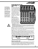
Channel Level Control
First adjust the Main Level control to the shaded area (7 to 8 on the level scale). With a sig-
nal applied to the input, adjust the Channel Level control until the appropriate audio level is
heard out of the loudspeaker. If the Clip LED for the channel that you are adjusting is blink-
ing then turn the Channel Level down until the Clip LED blinks occasionally. This will ensure
that the signal level fits comfortably within the channel strip's headroom ~ low enough to
prevent distortion, and yet high enough to preserve the signal to noise ratio. This control
covers a wide range, so it may seem rather sensitive until you're used to it.
3-Band EQ
Equalization is varied by three controls labeled High, Mid, and Low. Each control can either boost
or cut the amplitude of its frequency band by 15dB. This is a considerable amount of gain change,
roughly equivalent to a 150% variation in audible loudness. It is therefore wise to use boost set-
tings of not more than +3dB to +6dB in order to avoid feedback and/or distortion.
On the other hand, -15dB of CUT-capability can come in handy for solving certain microphone or
line problems. For example, substantial Low and High cuts can help get rid of feedback plus puff-
ing and thumping noises from harmonica microphones. Flattop guitar microphones or transducers
can often benefit from a slight Mid cut to fatten the sound, and direct or miked bass inputs usually
benefit from a fairly substantial Low cut to avoid main system distortion.
Channel AUX Level Control
The Channel AUX Level control varies the amount of post-equalizer, channel signal sent to
the master AUX bus. The output of the AUX bus goes first to the AUX Send Level Control,
then to the AUX Send jack.
Pan (or balance) Control
This control directs the post-fader mono output of the channel to the Left and Right Main
masters. In a stereo setup, the Pan should be set to the 12 o'clock position so that the
aural image of the audio signal is in the center of the stereo listening field. The pan control
can be turned clockwise or counterclockwise to move the image of the channel's audio signal
to the right or the left channel.
Clip LED
The channel Clip LED watches all the active electronic stages in the channel circuit. Whenever
any stage's signal peak approaches clipping to within 3dB, the Clip LED circuitry captures and
displays this event. See under Channel Level control for more about this feature.
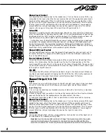
Channel Strips 5/6 & 7/8
Inputs
Each channel has a pair of RCA input jacks for the left and right input signals. Using jack adapt-
ers such as ¼-inch phone to RCA will allow any line level signal to enter these channels.
Input Wiring tips:
1. For all input conductivity use shielded wire only. Cables with a foil shield or a high-den-
sity braid are better.
2. When changing input connections, turn down the level controls on the mixer to eliminate
pops and thumps out of the loudspeakers as the cable contacts the mixer.
3. Keep input connection cables as short as possible to minimize noise and hum pick-up.
Channel Level Control
First adjust the Main Level control to the shaded area (7 to 8 on the level scale). With signal
applied to the input, adjust the Channel Level control until the appropriate audio level is
heard out of the loudspeaker. If the Clip LED for the channel that you are adjusting is blink-
ing then turn the Channel Level down until the Clip LED blinks occasionally. This will ensure
that the signal level fits comfortably within the channel strip's headroom ~ low enough to
prevent distortion, and yet high enough to preserve the signal to noise ratio.
2-Band EQ
Two controls labeled High, and Low vary equalization. Each control can either boost or cut
the amplitude of its frequency band by 15dB.
User tip
: Use the channel EQ controls to "shape" the desired sound for the audio
coming into that channel. The source for channels 5/6 may be different than the
source for channels 7/8. That's why there are separate tone controls for each chan-
4
HI
MID
LOW
PAN
A
U
X
HI
MID
LOW
PAN
A
U
X
MIC / LINE
INPUT
MIC / LINE
INPUT
CLIP
CLIP
1
2
1
3
3
6
6
9
9
12
12
15
15
3
3
6
6
9
9
12
12
15
15
3
3
6
6
9
9
12
12
15
15
LE
VE
L
4 5 6
7
3
8
2
9
1
10
0
4 5 6
7
3
8
2
9
1
10
0
3
3
6
6
9
9
12
12
15
15
3
3
6
6
9
9
12
12
15
15
3
3
6
6
9
9
12
12
15
15
LE
VE
L
4 5 6
7
3
8
2
9
1
10
0
4 5 6
7
3
8
2
9
1
10
0
LOW
HI
AUX
LE
VE
L
LOW
HI
AUX
LE
VE
L
CD / LINE / TAPE
CD / LINE / TAPE
STEREO
STEREO
INPUT
INPUT
CLIP
CLIP
7/8
5/6
3
3
6
6
9
9
12
12
15
15
3
3
6
6
9
9
12
12
15
15
4 5 6
7
3
8
2
9
1
10
0
4 5 6
7
3
8
2
9
1
10
0
3
3
6
6
9
9
12
12
15
15
3
3
6
6
9
9
12
12
15
15
4 5 6
7
3
8
2
9
1
10
0
4 5 6
7
3
8
2
9
1
10
0
Summary of Contents for M8
Page 22: ...20 ...


