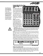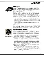
5. The Phones/Control Room level controls the headphone amplifier gain. The Phones/Control
Room Assign-switches allow the user to select channels 1 - 4, or stereo channel 5/6, or
stereo channel 7/8, or any combination, or all three selections and send the audio signal to
the Phones/Control Room level control. This feature allows the user to monitor the separate
channel audio signals, and listen to the sound quality of individual musical instruments, or
press all three Control Room Assign-switches down and use the Phones/Control Room out-
put to feed a control room monitor, or an amplifier to loudspeakers located in another room
(another audio zone). To "cue" an audio track before playing the music through the mixer,
turn down the Channel Level to 0 and plug your headphones into the phone jack on your
source audio equipment. When you have found the starting point of your music passage,
pause the player, return the Channel Level to the original turned-up setting and press play on
the source equipment at the appropriate time.
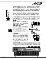
If you are sending the PHONES/CTRL ROOM signal to another piece of audio equipment, use
a TRS cable (in this case to be used as a stereo cable), as the left and right channel signals
are present in the PHONES/CTRL ROOM jack. If a mono cable is used, the left channel signal
will get shorted to ground by the mono cable inside the jack. This could result in the head-
phone amplifier becoming hot and the right channel audio signal becoming distorted.
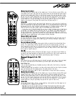
Level Meters
These meters indicate the Left and Right Main bus
audio levels. If either or both of the +3dB amp clip
lights at the top of the level meters are flashing
TOO MUCH of the time, lower the Main Level control
to avoid possible distortion on peaks.
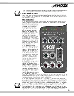
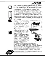
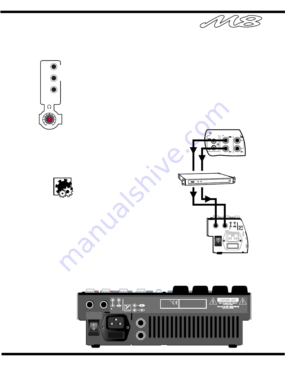
Amplifier Inputs L & R
These are switching jacks that enable you to directly
access either or both channels of the built-in power
amplifier while disconnecting the normally connected
source the Main EQUALIZER. This permits you to
insert an external-EQ, a processor /crossover (e.g.
élite) or a compressor/limiter between the mixer sec-
tion's Main OUTPUTS and the AMP 1 & AMP 2 INPUTS
thus providing the 100% signal processing.
Power Amplifier
The M8 has a built-in 170-watt stereo power amplifier.
Each channel has an input sensitivity of +4dBv (1.4
volts RMS) for full-power output and each can deliver
over 85 watts into a 4-ohm speaker load. These ampli-
fiers incorporate computer designed internal heatsinks
and a variable-speed fan which automatically provides
quiet operation consistent with cooling requirements.
Cool air is drawn into the front of the mixer, and heat-
ed air is expelled out of the back. Even at maximum
power, this arrangement results in quiet, dependable
performance.
PLEASE NOTE: The air vents at the front and rear of the mixer are essential for
proper operation . Blocking the free flow of air through the mixer will result in sys-
tem shutdown due to overheating. Repeated overheating may eventually cause
damage. Please keep the vents free of obstructions.
6
P O W E R
O N
TYPE: YS1024
FUSE:
T3.15A
1b5
85 WATTS
MIN 4-OHMS
PER CHANNEL
SPEAKER OUTPUTS
Designed & Manufactured by
YORKVILLE SOUND • TORONTO, CANADA
100V-240V
50/60Hz
200VA
AMPLIFIER
INPUT
CAUTION: REPLACE WITH
SAME TYPE FUSE AND RATING
ATTENTION: UTILISER UN FUSIBLE DE
RECHANGE DE MEME TYPE ET CALIBRE
C
H
A
N
N
EL
S
1-4
5/6
7/8
PHONES /
CTRL ROOM
ASSIGN
LE
VE
L
4 5 6
7
3
8
2
9
1
10
0
P O W E R
O N
AMPLIFIER
INPUT
Main Out on M8
Extrenal Effects Unit
Amp In on M8
MAIN OUT
RECORD OUT
AUX RTN
Summary of Contents for M8
Page 22: ...20 ...


