background image

MICROMIX

MICROMIX

9. P

POWER L

LED &

& T

THE S

SWITCH 

The 

POWER LED

lets you know that the 

MP10DS

is plugged in and turned on. The 

AC

power

on/off

switch is on the rear panel of the unit.

10. P

PHANTOM P

POWER

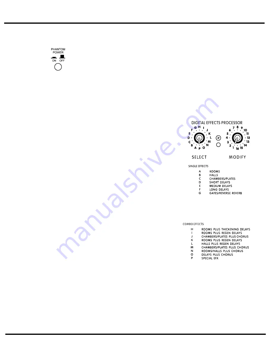
The 

PHANTOM

power 

LED

indicates that 

24 volts

of 

DC

phantom

power is present on all the

XLR

microphone inputs to power condenser microphones. Regular dynamic mics may be con-

nected while the 

PHANTOM POWER

is activated without encountering problems. The 

PHAN-

TOM POWER

push-button is located on the rear panel.

DIGITAL E

EFFECTS P

PROCESSOR

1. D

DIGITAL E

EFFECTS P

PROCESSOR S

SELECT &

& M

MODIFY C

CONTROLS

The 

SELECT

control selects from 

16 banks

of reverb sounds, delays and other effects. Settings

A

through 

G

represent single reverbs or echo delays. Settings

H

through 

P

are combined or

combo

effects where two or more effects are blended together. Simply rotate the 

SELECT

con-

trol to the basic type of effect you prefer. This is a continuous type of control so you may sim-
ply rotate it in either direction to reach the desired setting. Lists of effects banks appear in this
manual and on the front panel of the 

MP10DS.

Each 

bank

of effects contains 

16

individual effect variations. The 

MODIFY

control selects

each one of these variations. For example, if 

bank E

(Medium Delays), has been selected, position 

1

will

give you 

200

milliseconds of delay, and positions 

2

through 

16

will give you progressively longer delays

up to 

375

milliseconds. 

Bank P

is the exception to

this rule. It consists of sixteen different 

special effects

,

such as pitch shift up, or down, detune flanger, etc.

2. E

EFFECTS C

CLIP L

LED

Situated between the 

SELECT

and 

MODIFY

controls,

the 

CLIP LED

indicates that the digital processor is

receiving an input signal which is too strong, possibly
resulting in distortion. For maximum dynamic range,
the 

Clip LED

should flash briefly, but only on high-

energy transients such as loud snare drum hits. If
there is too much 

CLIP

activity, turn down the chan-

nel 

EFX

controls.

3. E

EFFECTS T

TABLES

See rear inside cover for effects tables.

5

Summary of Contents for MP10DS

Page 1: ...OWNER S MANUAL MANUEL DE L UTILISATEUR o mp10ds 2v0 qxd 09 29 00 jb ...

Page 2: ... DE CHOC ELECTRIQUE N ENLEVEZ PAS LE COUVERT OU LE PANNEAU ARRIERE NE CONTIENT AUCUNE PIECE REPARABLE PAR L UTILISATEUR CONSULTEZ UN TECHNICIEN QUALIFIE POUR L ENTRETIENT Veuillez lire le manuel Il contient des informations qui devraient êtres comprises avant l opération de votre appareil Conservez S V P ces instructions pour consultations ultérieures Emballage Conservez la boite au cas ou l appar...

Page 3: ... high impedance microphones guitars amplifier Line outputs synthesizers electric pianos etc Note when connecting a balanced signal employ balanced patch cables with a ring tip sleeve stereo 1 4 plug on the mixer end Channels 7 8 and 9 10 have Left Right 1 4 BAL LINE IN jacks plus Left Right TAPE CD LINE RCA type inputs Either the 1 4 or RCA type input not both may be used to connect a stereo tape ...

Page 4: ...A system and the RECORD OUT jacks In standard operating mode with the built in effects working you would connect a regular on off footswitch e g Yorkville model IFS 1A to the EFX FOOTSWITCH SEND jack to turn the internal effects on and off See the sec tion EFX FOOTSWITCH SEND later in this manual for more information Alternatively this signal can be connected to the input of an external stereo eff...

Page 5: ... MONITOR LINE OUT signal 5 M MAIN L LINE O OUT A AMP I IN J JACKS These jacks can serve a variety of patching and routing purposes They are positioned in the signal path after the MP10DS main graphic equalizer and are therefore regulated by it i e they are post EQ The main bus signals are available at line level not speaker level use the SPEAKER outputs on the back panel to drive speakers from the...

Page 6: ... then solder a 2 2k Ohm resistor across the plug to be inserted in an AMP IN jack It would then be advisable to identify either the LINE OUT or AMP IN plugs on both cords perhaps with tape or a dab of paint on the plug jacket 7 M MONITOR L LINE O OUT J JACK The monitor bus output signal is available at line level not speaker level from the MON OUT jack and would normally be patched to the input of...

Page 7: ...fer This is a continuous type of control so you may sim ply rotate it in either direction to reach the desired setting Lists of effects banks appear in this manual and on the front panel of the MP10DS Each bank of effects contains 16 individual effect variations The MODIFY control selects each one of these variations For example if bank E Medium Delays has been selected position 1 will give you 20...

Page 8: ... sound system operators however usually strive to use a minimum of equalization for this purpose or for boosting the bass Instead they use very minimal sound shaping adjust ments to ensure that the threat of feedback and distortion will also be minimal MP10DS R REAR P PANEL 1 A A B B S SPEAKER O OUTPUTS H HEATSINKS Each of the MP10DS dual power amplifiers has two 1 4 jacks for speaker connections ...

Page 9: ...nother one from the EQ s output to the input of the monitor power amp 8 Position your main PA speakers at the front of the stage pointing directly out at the audi ence Position your monitor speakers on the stage floor in front of the mic stands pointing up at the backs of the mics Remember to use cardioid or uni directional mics to reduce the threat of monitor feedback 9 During a sound check with ...

Page 10: ... 10k Ohms Unbalanced input impedance RCA 5k Ohms Balanced CMRR min 35dB typical 50dB Frequency response 36 dB gain 3 dB 20 Hz to 20 KHz Signal path distortion less than 0 1 20Hz 20KHz Channel Clip LED threshold 5 dB before clipping Channel EQ adjustment range 15 dB Graphic EQ adjustment range 12 dB Phantom Power 24 VDC AMPLIFIER Frequency response 3 dB 20 Hz to 20 KHz Gain 24 dB Input sensitivity ...

Page 11: ...prises d entrées équilibrés haute impédance Ces prises d entrées de niveau ligne sont électroniquement équilibrés Elles accepteront aussi toutefois des câbles équilibrés ou déséquilibrés provenant de microphones haute impédance guitares sortie ligne d amplificateur synthétiseurs pianos électriques etc notez Lors de branchement avec signal équilibré utilisez des câbles équilibrés avec prise bague p...

Page 12: ...IN de canal Normalement le signal de sortie du bus d effets est intérieurement acheminé au PROCESSEUR D EFFETS NUMERIQUE Le cas échéant le contrôle EFX réglerait l intensité des effets internes sur le son de ce canal acheminé au mélange principal du système et aux prises de sortie RECORD OUT En mode d opération standard lorsque vous utilisez les effets internes il est possible de brancher un inter...

Page 13: ...ORTIE RECORD 4 C CONTRÔLE M MAÎTRE M MONITOR E EFX Le contrôle maître MONITOR EFX règle la somme de signal allant de la sortie du PROCESSEUR interne D EFFETS NUMERIQUES au bus de mélange MONITEUR où il est mélangé avec les signaux dépourvu d effet provenant du contrôles d envoi de canal MON SEND Il contrôle l intensité générale d effets du signal de la SORTIE LIGNE DE MONITEUR 5 P PRISES S SORTIE ...

Page 14: ... disponible à partir des jacks MON OUT Il est normalement relié à un amplificateur de puissance mono ou à un des cannaux d un amplificateur stéréo de façon à entraîner un système d enceintes pour retour de scène Le MP10DS n est pas doté d égalisation interne pour le mélange de retour de scène Il est parfois donc préférable d insér er un égalisateur graphique entre la sortie MON OUT et l entrée de ...

Page 15: ...s listes de banques d effets apparaissent dans ce manuel et sur le panneau avant du MP10DS Chaque banque d effets contient seize variations individuelles d effet Le contrôle MODIFY sélec tionne chacune de ces variations Par exemple si la banque E retards moyens a été sélectionné un réglage du contrôle à la position 1 vous donnera 200 millisecondes de retard Les positions de 2 à 16 vous donneront d...

Page 16: ... système à des fins artistiques Chaque bande est ajustée de façon à obtenir une sonorité optimum Généralement les opérateurs les plus expérimentés s efforcent cependant d employer un minimum d égalisation pour obtenir les résultats voulus Ils minimisent plutôt l emploi des ajustements de façon à réduire les possibilités de feedback et d écrêtage PANNEAU ARRIERE M MP10DS R REAR 1 D DISSIPATEURS D D...

Page 17: ...ez des enceintes 4 ohms vous pouvez en brancher une à chaque canal Il est aussi possible de brancher une ou deux enceintes 8 ohms pour retour de scène à une sortie de canal d amplificateur et deux enceintes pour PA principal 8 ohms à l autre canal Raccordez maintenant un câble blindé à partir de la prise DE SORTIE DE MONITEUR jusqu à l entrée de l amplificateur choisis pour alimenter les retours d...

Page 18: ...corporé 16 CARACTERISTIQUES SPECIFICATIONS LE MIXEUR Entrées type XLR équilibrées 6 Entrées type équilibrées 10 Entrées type RCA déséquilibrées 2 paires stéréo Égalisateur aux canaux Haute Moyenne Basse Effets aux canaux Oui Envois au retour Pre Gain Le contrôle de pan 6 canal 1 6 sortie principale Stéréo ou Mono Sortie de retour Oui Entrée à l amplificateur 2 A B envois aux effets Oui Effets au m...

Page 19: ...s slap delay 13 5 0s Dark Large Hall 80ms slap delay J CHAMBERS PLA TES THICKENING DELA YS 1 0 8s Warm Chamber 50ms doubling delay 2 0 8s Bright Chamber 50ms doubling delay 3 1 2s Warm Chamber 60ms doubling delay 4 1 2s Bright Chamber 70ms slap delay 5 1 5s Warm Chamber 70ms slap delay 6 1 5s Bright Chamber 80ms slap delay 7 2 5s Warm Chamber 80ms slap delay 8 2 5s Bright Chamber 100ms slap delay ...

Page 20: ... Falls New York 14305 USA Voice 716 297 2920 Fax 716 297 3689 WORLD HEADQUARTERS CANADA Yorkville Sound 550 Granite Court Pickering Ontario L1W 3Y8 CANADA Voice 905 837 8481 Fax 905 837 8746 Quality and Innovation Since 1963 Printed in Canada WEB www yorkville com ...

Reviews: