background image

U.S.A. 

Yorkville Sound Inc. 

4625 Witmer Industrial Estate 

Niagara Falls, New York 

14305 USA 

Voice: (716) 297-2920 

Fax: (716) 297-3689 

WORLD HEADQUARTERS 

WEB ACCESS: http://www.yorkville.com 

CANADA 

Yorkville Sound 

550 Granite Court 
Pickering, Ontario 

L1W-3Y8 CANADA 

Voice: (905) 837-8481 

Fax: (905) 837-8746 

Quality and Innovation Since 1963

Printed in Canada 

SERVICE MANUAL 

SB110/SB112/SB115

TYPE: YS1109

SMT Disclaimer

Due to the complex nature of the use of SMT installed components 

in Yorkville equipment, we highly caution all service technicians in 

attempting to repair or replace SMT factory installed components.

Many of these components may be glued prior to initial soldering.

Replacing SMT components requires expensive

specialized de-soldering equipment and training.

Yorkville Sound will repair and replace defective SMT components 

to ensure proper quality assurance and installation is maintained.

Summary of Contents for SB110

Page 1: ...RVICE MANUAL SB110 SB112 SB115 TYPE YS1109 SMT Disclaimer Due to the complex nature of the use of SMT installed components in Yorkville equipment we highly caution all service technicians in attempting to repair or replace SMT factory installed components Many of these components may be glued prior to initial soldering Replacing SMT components requires expensive specialized de soldering equipment ...

Page 2: ...a propre ventilation Ne procédez pas à l installation près de source de chaleur tels que radiateurs registre de chaleur fours ou autres appareils incluant les amplificateurs qui produisent de la chaleur Les dispositifs marqués d une symbole d éclair sont des parties dangereuses au toucher et que les câblages extérieurs connectés à ces dispositifs de connection extérieure doivent être effectivés pa...

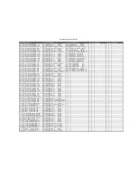
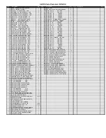
Page 3: ...__1U 63V 5 CAP T R RAD 2FLM 3 8729 4 X 3 8 FLAT QUAD TYPE A JS500 BLK 2 5257 __2U2 63V 20 CAP T R RAD 2EL 1 8753 10 X 1 2 PAN QUAD TY A JS500 BLACK 20 5942 __3U3 100DC10 CAP BLK RAD POLYE FLM 1 8756 10 X 3 4 PAN PH TYPE A BLACK OXIDE 4 5282 _10U 16V 20 CAP T R 5X7MM 2NP 4 8727 10 X 1 PAN PH TYPE A JS500 BLACK 4 5945 _10U 63V 20 CAP T R RAD 2EL 1 9001 4 40 X 5 16 PAN PH MS ZN C W STARWA 4 5631 _22U...

Page 4: ... R RES C34 5410 100P 100V 10 CAP T R BEAD NPO R25 4847 W250 2K2 5 T R RES C35 5234 470N 63V 10 CAP T R RAD 2FLM R26 4800 W250 10K0 1 T R RES C36 5226 _68N 100V 5 CAP T R RAD 2FLM R27 4800 W250 10K0 1 T R RES C37 5222 _33N 100V 10 CAP T R RAD 2FLM R28 4804 W250 3K 5 T R RES C38 5231 220N 63V 5 CAP T R RAD 2FLM R29 4919 W250 2K05 1 T R RES C39 5230 180N 63V 5 CAP T R RAD 2FLM R3 4800 W250 10K0 1 T R...

Page 5: ...T R RAD 2EL 1 8753 10 X 1 2 PAN QUAD TY A JS500 BLACK 20 5942 __3U3 100DC10 CAP BLK RAD POLYE FLM 1 8756 10 X 3 4 PAN PH TYPE A BLACK OXIDE 4 5282 _10U 16V 20 CAP T R 5X7MM 2NP 4 8727 10 X 1 PAN PH TYPE A JS500 BLACK 4 5945 _10U 63V 20 CAP T R RAD 2EL 1 9001 4 40 X 5 16 PAN PH MS ZN C W STARWA 4 5631 _22U 50V 20 CAP T R 6X7MM 2EL 2 8742 4 40 X 3 8 PAN PH TAPTITE JS500 2 5267 100U 25V 20 CAP T R RA...

Page 6: ...R22 4639 W250 4K99 1 T R RES C36 5226 _68N 100V 5 CAP T R RAD 2FLM R23 4800 W250 10K0 1 T R RES C37 5222 _33N 100V 10 CAP T R RAD 2FLM R232 4808 W250 2K 5 T R RES C38 5231 220N 63V 5 CAP T R RAD 2FLM R24 6110 W250 1K0 1 MINI MF T R RES C39 5231 220N 63V 5 CAP T R RAD 2FLM R25 4847 W250 2K2 5 T R RES C4 5417 330P 50V 10 CAP T R BEAD NPO R26 4800 W250 10K0 1 T R RES C40 5204 _10N 100V 10 CAP T R RAD...

Page 7: ...0 5257 __2U2 63V 20 CAP T R RAD 2EL 1 8756 10 X 3 4 PAN PH TYPE A BLACK OXIDE 4 5942 __3U3 100DC10 CAP BLK RAD POLYE FLM 1 8727 10 X 1 PAN PH TYPE A JS500 BLACK 4 5282 _10U 16V 20 CAP T R 5X7MM 2NP 4 9001 4 40 X 5 16 PAN PH MS ZN C W STARWA 4 5945 _10U 63V 20 CAP T R RAD 2EL 1 8742 4 40 X 3 8 PAN PH TAPTITE JS500 2 5631 _22U 50V 20 CAP T R 6X7MM 2EL 2 8861 4 40 X 3 8 PAN PH MS JS500 2 5267 100U 25...

Page 8: ...09 __4N7 250V 5 CAP T R RAD 2FLM R2 4867 W250 270R 5 T R RES W3 2371 2 CIR WS HEADER 0 156 C34 5410 100P 100V 10 CAP T R BEAD NPO R20 4800 W250 10K0 1 T R RES W4 2370 7 CIR PH HEADER 2MM C35 5212 100N 63V 5 CAP T R RAD 2FLM R21 6123 W250 20K0 1 MINI MF T R RES W5 4056 2 CIR XH HEADER 0 098IN C36 5226 _68N 100V 5 CAP T R RAD 2FLM R22 4639 W250 4K99 1 T R RES W6 4056 2 CIR XH HEADER 0 098IN C37 5222...

Page 9: ...3 XLR MALE PCB MT HORZ MTHOLE V SNAP 1 11 3428 8 3 18 SJT AC LINE CORD REMOVABLE 1 12 8522 RUBBER BUMPER WITH WASHER SMALL 4 13 8570 CORNER 2 LEGS NOTCED BLACK POWDER 8 14 3645 RECEPTACLE INLET 1 15 4173 FAN 40MM X 10MM 4 5CFM 12VDC 5MA 1 16 7555 12 4R 200WPGM SPEAKER 1 17 7552 _8R 30W TWEETER PIEZO S 1 18 8451 10 0 STRAP HANDLE BLACK METAL ENDC 1 19 3698 SPST ROKR SW QUIK 180 AC PWR BL BL 1 20 10...

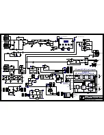
Page 10: ...ltering ch 2 DC DC Converter with isolation R33 1 4W 270R R4 1 4W 270R Vo ch2 Audio out GND 2 Vs aux Vd aux 8 V 4 V U1 C 63V C26 100N THERMISTOR 63V C27 100N 8 V 4 V U14 C R81 1 4W 10K0 RAD 2in 100U C3 25V 4 V 11 V U8 E 33N C45 100V 1 4W 10K0 R136 1 4W 3K R28 1 4W 4M7 R30 R150 1 4W 30K U1 B TL072 63V 1U C70 1 4W 22K R38 63V 1U C23 63V 10U C21 R26 1 4W 10K0 LD1 6554 POWER BLU ICE50SAX2 Black MPSA13...

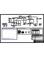
Page 11: ...93 R169 1 4W 15K C9 16V 10U INPUTS M1 63V C30 100N 11 V 4 V U2 E DIP8 TL072CP YS 6882 MC33078P YS 6840 DIP14 MC33079P YS 6804 R12 1 4W 6K8 R69 1 4W 100K U2 C MC33079P U2 B MC33079P B C TO 92 E MPSA13 YS 5105 MPSA42 YS 5113 R75 1 4W 6K98 U3 A MC33079P U2 D MC33079P POTENTIOMETERS AND KNOBS MAINS VOLTAGE INPUT SETTING NA CE U3 D MC33079P M 50K 1B LIN 4494 P4 TREBLE M 50K 1B LIN P3 LOW MID 4494 M 50K...

Page 12: ...BlankSize 12000x9000 INTO WAVE ...

Page 13: ...MAINS VOLTAGE INPUT SETTING NA CE Remove this piece Break this connection here 1 Add RTV to C6 2 R48 R49 R50 R52 R56 and R57 are used to level up their respective pots during wave soldering 3 Break the connection of XLR J4 as per diagram 4 Please break the panel before testing 5 Do not forget to add a 2 pin header to the thermistor harness assembly as shown below ...

Page 14: ...4 V02 N N N PC 8734 D2 D5 YS 6438 1N4007 added across the PC 8738 C20 C22 changed from 33P to 100N YS 5212 N 08 JAN 2013 V01 M1503 DATABASE HISTORY SMALL BLOCK SB110 FIRST PRODUCTION RELEASE PC8540 Several changes See PC V03 PC8550 Routed auxiliary signal to headphones ML 09 JUL 2013 11 SEP 2014 PC 8696 Replace R29 2K05 to 4K99 YS 4639 FUNCTION KNOB REF MODEL S PART R R R P5 P6 P8 P1 P3 P4 F F F F...

Page 15: ...2 R33 1 4W 270R R4 1 4W 270R Audio out GND Vs aux Vd aux 8 V 4 V U1 C 63V C26 100N 63V C27 100N 4 V 11 V U9 E R81 1 4W 10K0 1 4W 2K R5 TO92 MPSA42 Q1 5113 63V C42 100N 4 V 11 V U8 E 33N C45 100V 1 4W 10K0 R136 1 4W 4M7 R30 1 4W 3K R28 R150 1 4W 30K 63V C20 100N U1 B TL072 1 4W 22K R38 63V C23 1U 63V C21 10U R26 1 4W 10K0 R41 5 0W 10R LD1 POWER 6554 BLU ICE50SAX2 MPSA13 Q2 TO92 5105 50V C81 12N R17...

Page 16: ...3079P 11 V 4 V U2 E 63V C30 100N DIP8 TL072CP YS 6882 MC33078P YS 6840 DIP14 MC33079P YS 6804 R53 1 4W 200K R69 1 4W 100K R12 1 4W 6K8 U2 B MC33079P U2 C MC33079P R54 1 4W 200K B C TO 92 E MPSA13 YS 5105 MPSA42 YS 5113 U3 A MC33079P U2 D MC33079P POTENTIOMETERS AND KNOBS MAINS VOLTAGE INPUT SETTING NA CE M 4494 P4 TREBLE 50K 1B LIN M P3 LOW MID 50K 4494 1B LIN M 50K 1B LIN P5 4494 BASS S G TO 92 D...

Page 17: ...N 2K 1K0 10K0 2K49 10K0 100N 47N 100K 4K7 12N BLU 6K8 50K 1B LIN 0 10N 18N 470R 1 2W 50K 1B LIN 10N 470R 1 2W 50K 1B LIN 680P 15K 10U 16V 33N 22U 50V 1K0 4K7 100P 10N 6K98 6K98 220N MC33079P 2K 20K0 2K49 10K0 10K0 681R 22U 50V 100N 100K 47K 2K2 6K8 3K3 10U 16V 47K 3 2K2 4K7 470R 1 2W 470R 1 2W RED 5K 10C 1K0 4K99 470R 1 2W 470R 1 2W 33N 50K 1B LIN 10K 5B LIN 47K MC33078P MC33079P BUTTON BUTTON DPD...

Page 18: ...e used to level up their respective pots during wave soldering 3 Please break the panel before testing 4 Break the connection of XLR J4 as per diagram 5 Do not forget to add a 2 pin header to the thermistor harness assembly as shown below SET JUMPER P200 TO 115V FOR NA SET IT TO 230V FOR CE MAINS VOLTAGE INPUT SETTING NA CE Remove this piece Break this connection here ...

Page 19: ...0 10020 10020 STYLE M1505 POTS LIST SMALL BLOCK SB112 P41 P41 P41 P41 P41 P41 LOW EXPANDER 12 9 6 3 13 11 10 5 4 8 7 2 1 DATE VER DESCRIPTION OF CHANGE MODEL S D 11 SEP 2014 D V V N PC 8738 C20 C22 changed from 33P to 100N YS 5212 PC8696 Replace R65 2K05 to 4K99 YS 4639 on all V01 PCBs ML D D D 5 DEC 2014 13 MAY 2013 JAN 08 2013 02 MAY 2013 V V V V04 V02 V01 V N N N PC8540 Rework on V01 included G...

Page 20: ... 4W 270R R4 1 4W 270R GND Vo ch1 1 GND 63V C26 100N 8 V 4 V U1 C R81 1 4W 10K0 4 V 11 V U9 E 63V C32 100N 8 V 4 V U14 C 63V C42 100N 33N C45 100V 63V C101 100N 1 4W 4M7 R30 U1 B TL072 1 4W 10K0 R136 63V C23 1U R51 1 4W 30K R39 1 4W 1M LD1 BLU POWER 6554 U7 B MC33078P MPSA13 Q2 TO92 5105 ICE50SAX2 R175 1 4W 470R 50V C81 12N U9 A MC33079P U9 C MC33079P DC DC Converter with isolation Output stage and...

Page 21: ... 5B LIN 10K R169 1 4W 15K 11 V 4 V U3 E DIP8 TL072CP YS 6882 MC33078P YS 6840 DIP14 MC33079P YS 6804 R12 1 4W 6K8 U2 C MC33079P R53 1 4W 200K R54 1 4W 200K R69 1 4W 100K U2 B MC33079P B C TO 92 E MPSA13 YS 5105 MPSA42 YS 5113 U2 D MC33079P U3 A MC33079P POTENTIOMETERS AND KNOBS MAINS VOLTAGE INPUT SETTING NA CE U3 D MC33079P M 50K 4494 P4 1B LIN TREBLE M LOW MID P3 50K 4494 1B LIN M BASS 50K 1B LI...

Page 22: ...ClinchRepeats X1 0 000Y3 2 800 BlankSize 14250x9000 0 INTO WAVE ...

Page 23: ...TV to C6 and R233 2 R29 R31 R43 R45 R46 R47 and R48 are used to level up their respective pots during wave soldering 3 Please break the panel before testing 4 Break the connection of XLR J4 as per diagram 5 Do not forget to add the 2 pin header to the thermistor harness assembly as shown below MAINS VOLTAGE INPUT SETTING NA CE Remove this piece Break this connection here ...

Page 24: ...eadphones ML D D D D 11 SEP 2014 09 DEC 2014 08 JAN 2013 V V V V V04 V01 N N N PC 8734 D2 D5 YS 6438 1N4007 added across the PC8696 Replace R65 2K05 to 4K99 YS 4639 PC 8738 C20 and C22 changed from 33P to 100N YS 5212 N M1507 DATABASE HISTORY SMALL BLOCK SB115 FIRST PRODUCTION RELEASE 13 MAY 2013 V02 PC8540 Several changes See PC FUNCTION KNOB REF MODEL S PART R R R P8 R R P4 P5 P6 P1 P2 P3 F F F ...

Page 25: ...2 DATASHEET Version 1 3 ICEpower50ASX2 2x50W or 1x170W ICEpower Amplifier with integrated ICEpower Supply Block Diagram Figure 1 ICEpower50ASX2 block diagram Connection Diagram Figure 2 ICEpower50ASX2 connections ...

Reviews: