2
Setting 2 – 2 ms Delay
High pass frequency response (100 Hz – 20
kHz). Use when the delay of the subwoofer
is 2 ms. The UCS1P and UCS1 use this setting.
A 2ms delay is roughly the same as pushing
the U15P back by roughly 27 inches (68 cm).
Setting 3 – 3 ms Delay
High pass frequency response (100 Hz – 20
kHz). Use when the delay of the subwoofer
is 3 ms. The LS800P, LS808, LS1004 and TX9S
use this setting. A 3 ms delay is roughly the
same as pushing the U15P back by roughly
40.5 inches (102 cm).
Setting 4 – 8ms Delay
High pass frequency response (100 Hz – 20
kHz). Use when the delay of the subwoofer
is 8ms. The LS1208 uses this setting. An 8 ms
delay is roughly the same as pushing the
U15P back by roughly 107 inches (273cm).
3. LINK Jacks
The Link jacks are set up to make it easy to
hook up the Unity™ U15P to any audio sys-
tem with a minimum of hassles. All of the Link
jacks are connected in parallel, so you can
use any of them to daisy-chain other U15Ps
or powered subwoofers. For normal operation
connect the Unity™ U15P just like an ordinary
powered speaker.
The Unity™ U15P may be plugged in be-
fore or after other enclosures, such as pow-
ered subwoofers. The U15P does not alter
the signal to the daisy-chained enclosures
and will not draw any power from the host
mixer/processor driving them. Also, note that
an external crossover is not necessary when
using the Unity™ U15P.
As well as accommodating full range
enclosures, the Link jacks allow many U15Ps
to be connected in a string (parallel). There is
no practical limit to the number of U15Ps that
may be connected together.
4. Protection
The U15P has circuitry to prevent clipping,
over current from the power amplifier and
over excursion of the speaker. At high levels,
the limiter will limit the gain of the Unity™
U15P and hence, if the user attempts to set
the level control at a higher level than origi-
nally set; the resulting setting will be incorrect.
The level control should be set while operat-
ing at low levels (under 10 watts).
If the level control is set too high due to set-
ting it at high operating levels the input circuit
will clip and the dynamics of the bass will be
lost. The Red Clip indicator will signify when this
occurs. This can happen without audible distor-
tion since the filters will filter out the distortion.
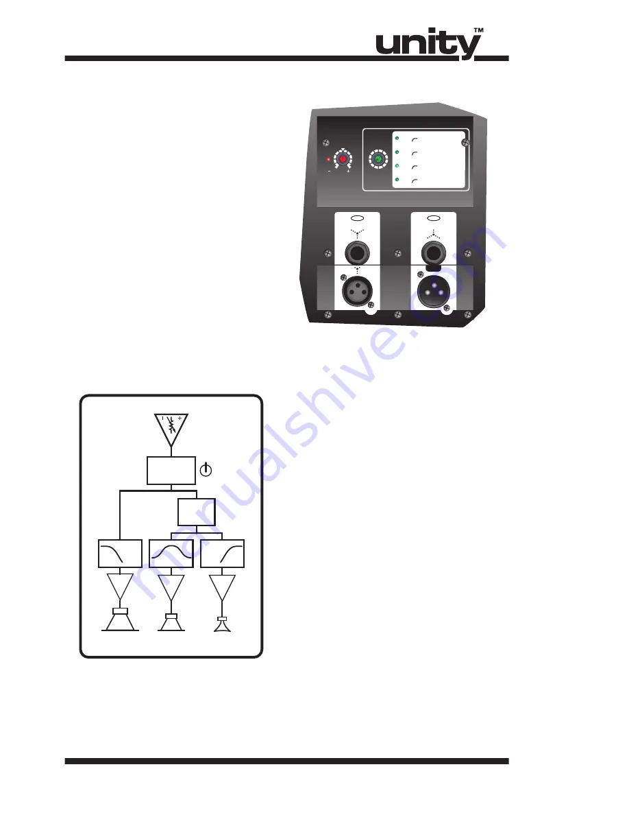
U15P
LEVEL
12
dB
00
PROGRAM
SELECT
CLIP
LIMIT
100Hz HPF, 24dB/Oct
2 ms Delay
3 ms Delay
8 ms Delay
1
2
3
4
25Hz HPF, 24dB/Oct
0 ms Delay
Full Range - No Sub
100Hz HPF, 24dB/Oct
100Hz HPF, 24dB/Oct
TIME ALIGNMENT SETTINGS
LINK
A-Z753 / 1v00
D S P
C O N T R O L L E D
INPUT
OUTPUT
BAL
BAL
Level
Fixed
Time Align
Delay
Program
Select
Hi
Mid
Lo
0, 2, 3, 8 ms
Enclosure
Delay Settings


