background image

5

Master Features

IMPORTANT!

The mixer section of the DJM806 will remain operational if the built-in power amp ever shuts 

down. The Main outputs would be used to connect another power amp in this instance. 

Master Fader 

The Master Fader determines the Main system’s level along with the channel faders. Leave 

at a low setting when playing quietly to reduce bus noise, and for mixing convenience.
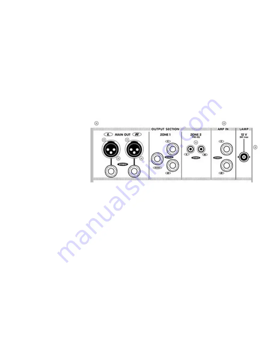
Main Out Connectors 

These balanced XLR and ¼-inch TRS (Tip-Ring-Sleeve) line-level outputs reflect the 

post-EQ, post-effects final mix signal as regulated by the Mains master fader. Connect 

external amplifiers here for main system reinforcement. Alternately you may use these 

connectors to patch a stereo crossover/processor (e.g. élite) or a compressor/limiter 

between the DJM806’s mixer section and built-in power amp. See under Amp In 

Jacks for patching instructions You may use balanced or unbalanced patch cables, 

however for quietest operation we recommend balanced cables.

Zone Output Section

Located in the upper right area, beside the Mains Output jacks, are the Zone 1 and 

Zone 2 line-level Outputs. These are Tip-Ring-Sleeve (balanced) ¼-inch connectors, 

which will accept unbalanced patch cords (but we recommend you use balanced 

cables for quietest performance). They are included for supplying signal to external 

power amplifiers or powered speakers, another mixer, triggered lights, etc. Each Zone 

has its own master Level control. 

Zone 1 has Left and Right outputs for driving a stereo amp/speaker setup, as well 

as a Mono output for driving a powered subwoofer or triggered lighting. The Zone 1 

signals go through the 7-band graphic equalizer via the Zone 1 EQ In/Out pushbut-

ton. With the In/Out feature, Zone 1 can bypass the onboard EQ if you are using it to 

run a separate amp/speaker system with different sound characteristics than the main 

speakers, perhaps near-field powered monitors.

Zone 2 is pre-EQ - i.e. it does not go through the graphic. It may be used for con-

nection to a tape deck, a second mixer or another amp/speaker system.

7-Band Graphic Equalizer & In/Out Button

The stereo, graphic equalizer can be switched In or Out of the Main signal with the 

bypass button located just above the Mains fader. Since there is up to +/-12dB of cut/

boost, you can use the EQ for controlling feedback quite effectively.

Summary of Contents for YS1010

Page 1: ...OWNER S MANUAL MANUEL DE L UTILISATEUR TYPE YS1010...

Page 2: ...VIS AFIN DE REDUIRE LES RISQUE DE CHOC ELECTRIQUE N ENLEVEZ PAS LE COUVERT OU LE PANNEAU ARRIERE NE CONTIENT AUCUNE PIECE REPARABLE PAR L UTILISATEUR CONSULTEZ UN TECHNICIEN QUALIFIE POUR L ENTRETIENT...

Page 3: ...ctors Terminology 3 pin microphone inputs are referred to as XLR connectors inch jack sockets are called phone connectors Balanced inch inputs or outputs are called TRS or Tip Ring Sleeve Master contr...

Page 4: ...ew channel signals via headphones before they go to the main system The Cue signal is post EQ so that the channel equal ization will be in effect through the headphones it is pre fader so that you may...

Page 5: ...to 20dB before crossfading to it and then simply turn it back up while completing the crossfade Effects Send Control The EFX send control varies the amount of post EQ post fader channel signal sent i...

Page 6: ...indications around 7 are roughly in the slide range where move ments produce the smallest most precise amounts of level change Above and below that area changes occur more quickly to provide fast max...

Page 7: ...the Zone 1 and Zone 2 line level Outputs These are Tip Ring Sleeve balanced inch connectors which will accept unbalanced patch cords but we recommend you use balanced cables for quietest performance T...

Page 8: ...dphones First depress the Cue button the LED will illuminate to indicate CUE on Now with the desired chan nel s EFX send controls turned up roughly half way the Headphone Crossfader set to Cue and the...

Page 9: ...ront and bottom rear of the mixer They are essential for proper operation Blocking the free flow of air through the mixer will result in system shutdown due to overheating After the DJM806 cools down...

Page 10: ...s means that if the DJM806 s power amp fails to come back on unlikely and you have a spare power amplifier available you can connect it to the DJM806 via the Main Out connectors b Because the amplifie...

Page 11: ...vel See under Gain Control and Cue Button for tips on setting the Gain 7 Still during the sound check connect your headphones to the Phones jack and turn up the Phones level Now you are ready to liste...

Page 12: ...Amp A 1 4 inch Jacks 2 Outputs Amp A Speakon 4 pin 1 Outputs Amp B 1 4 inch Jacks 2 Outputs Amp B Speakon 4 pin 1 Mixer Signal to Noise Ratio dB 100 Mixer Frequency Response Tone and EQ Flat 2dB 20 Hz...

Page 13: ...Terminologie Les entr es 3 tiges pour microphone sont appel es connecteurs XLR Les prises r ceptacles pouce sont appel es prises pouce Les prises sym triques pouce d entr e ou de sortie sont appel es...

Page 14: ...ur tre m lang avec les signaux provenant directement des canaux d entr e Bouton Cue La fonction Cue isole le signal du canal s lectionn et vous permet d couter l aide d un casque d coute les signaux d...

Page 15: ...Egalisateur 3 Bandes L galisation est r gl e par les trois contr les tiquet s High Mid et Low Chaque contr le peut renforcer ou couper l amplitude de sa bande de fr quence par 15 dB C est une gamme c...

Page 16: ...droit ou le mouvement du fader produit le plus petit changement de vol ume permettant donc des changements de niveau pr cis Au dessus et en dessous de la partie ombrag e les changements de niveau sont...

Page 17: ...roite pr s des jacks Main Out Ces jacks sym triques pointe bague manchon acceptent aussi des prises asym triques mais nous recommandons encore une fois l utilisation de c ble sym trique pour obtenir u...

Page 18: ...au signal principal Appuyez sur le bouton Cue situ sous la marque Effects Cue la DEL s illuminera indiquant que le cue est activ R glez le niveau du contr le EFX du canal d sir au milieu Glissez le C...

Page 19: ...libre r sultera en un arr t du syst me d a la surchauffe Une telle condition peut t t ou tard causer des dommages S V P gardez les bouch es d a ration libres d obstructions DEL d Ecretage Pour l Ampli...

Page 20: ...de puissance suppl mentaire disponible vous pouvez le branchez au DJM806 par les prises DE Sortie de Ligne R f rez vous la section Sortie de Ligne Pre et post EQ pour plus d information en ce qui conc...

Page 21: ...r glage du gain referez vous la section Contr le de Gain et Bouton Cue 7 Toujours durant le r glage du syst me branchez un casque d coute la prise Phone et ajustez le niveau Vous tes maintenant pr t...

Page 22: ...pouce Jacks 2 Sorties Amp A Speakon 4 tiges 1 Sorties Amp B 1 4 pouce Jacks 2 Sorties Amp B Speakon 4 tige 1 Mixeur Rapport Signal Bruit dB 100 Mixeur R ponse en Fr quence Contr le de Tonalit et gali...

Page 23: ...21...

Page 24: ...s slap delay 13 5 0s Dark Large Hall 80ms slap delay J CHAMBERS PLA TES THICKENING DELA YS 1 0 8s Warm Chamber 50ms doubling delay 2 0 8s Bright Chamber 50ms doubling delay 3 1 2s Warm Chamber 60ms do...

Page 25: ...aire de faire enregistrer votre nom aupr s de Yorkville Sound ou de votre d taillant Si pour une raison quelconque ce produit devient d fectueux durant les deux ann es qui suivent la date d achat init...

Page 26: ...625 Witmer Industrial Estate Niagara Falls New York 14305 USA Voice 716 297 2920 Fax 716 297 3689 WORLD HEADQUARTERS CANADA Yorkville Sound 550 Granite Court Pickering Ontario L1W 3Y8 CANADA Voice 905...

Reviews: