background image

2

‐                                 

EPDT-002g


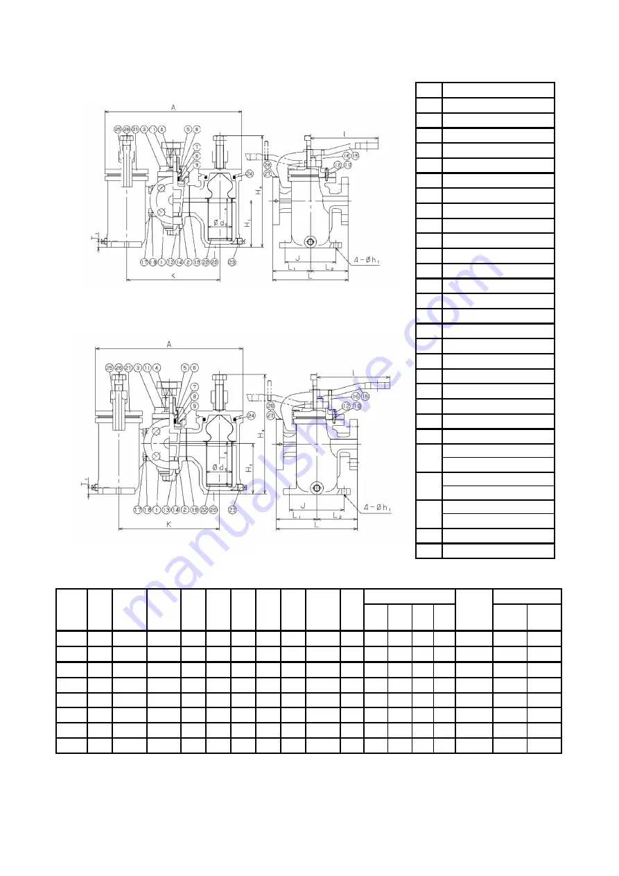
2.2 Structure, Dimensions and Weights


SW-10 


SW-10S


No. 

Parts name 

Body 

Cock 

Gland cover


Adjusting screw 

Washer 

Washer of Packing 

U-packing 

Packing Case 

Gasket 

10 

Gasket 

11 

Bolt 

12 

Pin 

13 

Cap 

14 

Gasket 

15 

Handle 

16 

Stopper 

17 

Bolt 

18 

Spring Lock washer 

19 

Gasket 

20 

Screen case


21 

Cover 

22 

Screen 

23 

Plug 

24 

Gasket (SW-10) 
O-Ring (SW-10S) 

25 

Stud Bolt (SW-10) 
Arm (SW-10S) 

26 

Nut (SW-10) 
Bolt (SW-10S) 

27 

Plate 

28 

Driving screw


Size 

L

1


L

2


H

1


Ha 

ds 

ls 

Anchor Base 

Plug 

Weight(kg) 


h

1

  T

1


SW-10 

SW-

10S 


  20A  200  100 

100 

126  280  292  363  180 

64.5  108  135  248  12  14  R 3/4 

23.9 

26.7 


  25A  200  100 

100 

126  280  292  363  180 

64.5  108  135  248  12  14  R 3/4 

25.1 

27.9 


  32A  205  102.5  102.5  126  280  292  363  180 

64.5  108  135  248  12  14  R 3/4 

26.1 

28.9 


  40A  245  122.5  122.5  134  306  316  390  180 

64.5  120  135  275  12  14  R 3/4 

34.0 

36.8 


  50A  245  122.5  122.5  134  306  316  390  180 

64.5  120  135  275  12  14  R 3/4 

35.9 

38.7 


  65A  285  130 

155 

155  356  345  450  240 

77 

140  160  311  15  20  R 3/4 

52.5 

54.6 


  80A  285  130 

155 

155  356  345  450  240 

77 

140  160  311  15  20  R 3/4 

53.0 

55.1 


100A  385  175 

210 

230  482  509  644  340  120 

210  225  430  19  20 

R 1 

117.0  124.3 

*Size of plug for stainless steel products are all R3/4.


Fig.1 Structure, dimensions and weights


Summary of Contents for SW-10

Page 1: ...injury Caution This symbol indicates a hazardous situation that if not avoided may result in minor or moderate injury or may result in only property damage Table of Contents Usage of the Product 1 1...

Page 2: ...1 Specifications Nominal Size 20A 100A Application Cold and hot water oil other non dangerous fluids Maximum Pressure 1 0MPa Maximum Temperature 80 Material Body Ductile Cast Iron Cock Stainless stee...

Page 3: ...W 10 SW 10S 20A 200 100 100 126 280 292 363 180 64 5 108 135 248 12 14 R 3 4 23 9 26 7 25A 200 100 100 126 280 292 363 180 64 5 108 135 248 12 14 R 3 4 25 1 27 9 32A 205 102 5 102 5 126 280 292 363 18...

Page 4: ...andard flow velocity depend on the relative kind of fluid Standard flow velocity of fluid Fluid Standard flow velocity Water Oil 2 m s 2 4 The above chart shows the standard flow velocity of relative...

Page 5: ...and cause malfunction 10 Fluid with viscosity stick the parts and lead to malfunction of the products 11 Before connecting the product in the piping be sure to remove foreign substances and scale fro...

Page 6: ...tightened together In this case hit the handle with plastic hammer Do not use iron hammer Turn the adjusting screw clockwise one or two times 2 Fit the pentagon hole of the handle to the cock Stopper...

Page 7: ...side the pipe and remove cover 21 Leakage at outside 1 Gasket O ring 24 is damaged 2 U packing 7 is damaged 1 Replace the gasket and O ring to new one 2 The product need to be disassembled and its par...

Page 8: ...f the screen case and cover Make sure that O ring is attached properly If the O ring is not installed properly O ring may be damaged and can be result in outer leakage 2 In case O ring is damaged or d...

Page 9: ...duct Yoshitake supplies the repair parts for 5 years otherwise individually agreed 3 This warranty does not cover the damage due to any of below 1 Valve seat leakage or malfunction caused by foreign s...

Reviews: