9
blue wires are for the L4 port.
LINE 5~8:
the Group 2 analog telephone line ports, which are also for connecting to the PBX only
if the EVM system is already equipped with an EVM83-4LC card.
Audio-In:
the audio input port. For more information, see “
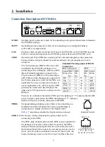
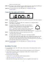
Connection Description of EVM-2XA
13VDC:
the main power connector, which is for connecting to the power transformer included in
the EVM-2X package.
BATT:
the backup-power connector, which is for connecting to a rechargeable battery
(12V/7AH is recommended).
PROG:
the programming-telephone port, which is for connecting to a
standard touch-tone telephone for on-site EVM programming or
connecting to a simple switch to be the Night switch.
determines whether the Night switch is allowed. If the
Night switch is allowed using, the closed-hour mode will be
activated in minutes after the switch is switched to the ON position.
MULT:
the multi-connection port, which is not used because the EVM
voicemail system is stand-alone.
LINE:
the analog telephone line ports, which are for connecting to the PBX.
The 6P4C-plug modular cable and the 6P4C socket (included in the package) are used
to connect the Line ports to the PBX's analog extension ports prepared for the voice
mail system. On the terminal block of the socket: the red and green wires are for the L1
port; the yellow and black wires are for the L2 port.
Audio-In:
the audio input port. For more information, see “
”.
Installation Procedure
1.
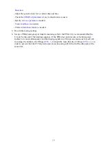
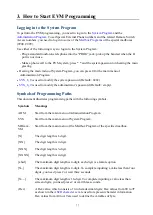
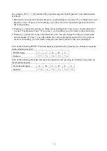
Power the EVM system. The “POW” light on the front panel will continually blink when the
system is ready.
2.
Connect the Line ports to the PBX's analog extension ports prepared for the EVM system.
3.
If the EVM was used before, delete inappropriate setting values by using the related
4.
Perform the EVM programming:
-
Create
to define the desired extension numbers.
-
operating-ways and feature codes
-
Define the Hook Flash length and define the Tone Cycle lengths for the Internal
L1 L1
L2
L2
LINE
PROG
MULT
13VDC
BATT
+ -
Audio
In
PROG
External Switch


