8
2.
Installation
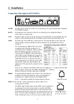
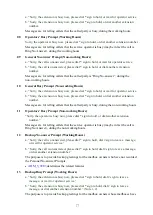
Connection Description of EVM-8XA
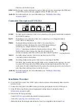
13VDC:
the main power connector, which is for connecting to the power transformer included in
the EVM-8X package.
BATT:
the backup-power connector, which is for connecting to a rechargeable battery
(12V/7AH is recommended).
LAN:
the hole, which is reserved for the LAN port of an EVM-NIC card. If the PBX uses the
LAN for voicemail integration, the EVM-8X system will need an EVM-NIC card.
COM:
the serial port. If the PBX uses a serial port for voicemail integration, the connection
between both serial ports should be made according to the pin assignment of each
connector.
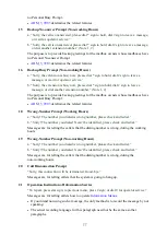
The 9-pin connector (DB9) of the wire cable
(included in the EVM-8X package) is for
connecting to this COM port, which is a DTE
(Data Terminal Equipment) connector; the
25-pin connector (DB25) is for connecting to
a DCE (Data Center Equipment) connector. If
the 25-pin connector is unfit for the PBX, you
might alter the wires connected on its pins or
use an appropriate wire cable. Anyway, a RD
pin must be connected to the TD pin of the
other end; a CTS pin must be connected to the
RTS pin.
There are two indicators beside the COM port: the lighting of “3” indicates that the RD
pin is correctly connected to the PBX; the lighting of “7” indicates
that the CTS pin is correctly connected to the PBX.
PROG:
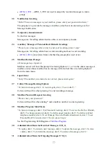
the programming-telephone port, which is for connecting to a
standard touch-tone telephone for on-site programming or
connecting to a simple switch to be the Night switch.
determines whether the Night switch is allowed.
LINE 1~4:
the Group 1 analog telephone line ports, which are for
connecting to the PBX.
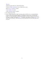
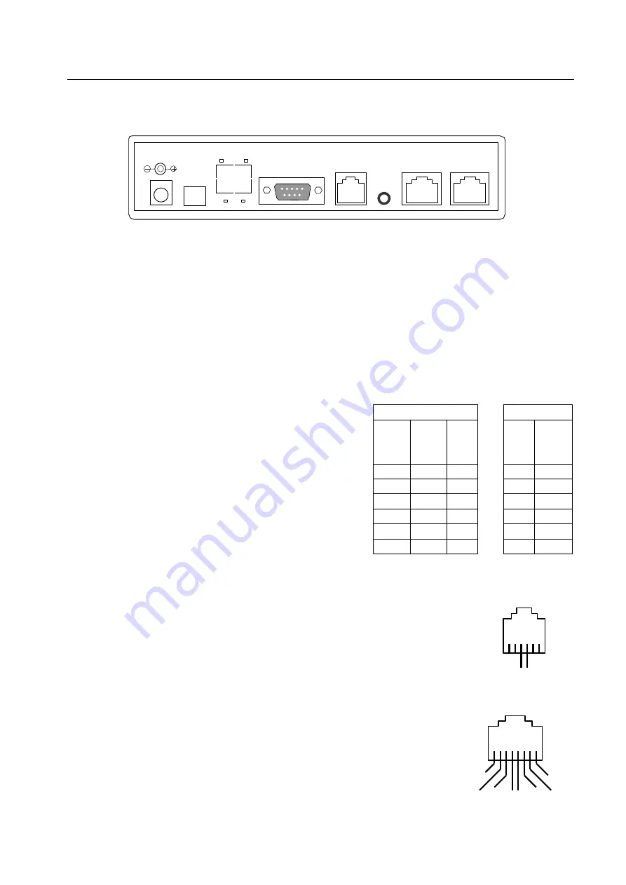
The 8P8C-plug modular cable and the 8P8C socket (included in
the package) are used to connect the Line ports to the PBX's
analog extension ports prepared for the voice mail system. On
the terminal block of the socket, the red and green wires are for
the L1 port, the yellow and black wires are for the L2 port, the
brown and orange wires are for the L3 port and the white and
Standard Pin Assignment of RS232
Connectors
DCE Connectors
DTE
Signal
Name
DB25
Pin
No.
DB9
Pin
No.
DB9
Pin
No.
Signal
Name
RD
3
2
2
TD
TD
2
3
3
RD
RTS
4
7
7
CTS
CTS 5
8
8
RTS
DSR 6
6
6
DTR
GND 7
5
–
5
GND
13VDC
LINE
1~4
PROG
BATT
+ -
3
7
LAN
COM
Audio
In
LINE
5~8
Line 1~4
L4
L4
L3 L2 L1 L1 L2 L3
PROG
External Switch


