background image


Hardware Operation Manual  


19

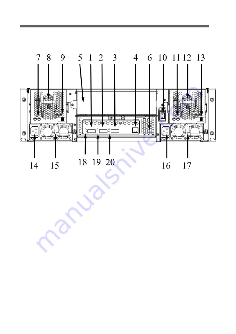
Y3-16S6JS6 


1. SAS CH 1/E (Expand out 2) 

2. SAS CH 0 (Expand In) 

3. SAS Expand Port (Expand out 1) 

4. Terminal 

5. Controller Box 2 (Reserved) 

6. Controller Box 1 

7. FAN failure indicator (Rear / Front) 

8. FAN Module 1 

9. FAN Module 1 Latch 

10. Power Switch 

11. FAN failure indicator (Rear / Front) 

12. FAN Module 2 

13. FAN Module 2 Latch 

14. AC inlet 1 & Latch 

15. Power Module 1 

16. AC inlet 2 & Latch 

Summary of Contents for 3 SAS

Page 1: ...Yotta 3 SAS SATA JBOD Enclosure User Guide Ver 1 0...

Page 2: ...ular purpose The information in this document is subject to change without notice We assume no responsibility for any errors that may appear in this document The manufacturer shall not be liable for a...

Page 3: ...l interference to radio or television reception which can be determined by turning the equipment off and on the user is encouraged to try to correct the interference by one or more of the following me...

Page 4: ...k servicing if the casing has been damaged DO NOT place or drop objects on top of the JBOD System and do not shove any foreign object into it DO NOT expose JBOD System to liquids rain or moisture DO N...

Page 5: ...chnology Guide to conventions Important information that users should be aware of the following icons This icon indicates the existence of a potential hazard that could result in personal injury damag...

Page 6: ...AR R RD D DW W WA A AR R RE E E I I IN N NS S ST T TA A AL L LL L LA A AT T TI I IO O ON N N 28 REPLACE THE CONTROLLER 28 HOT SWAPPING TO REPLACE THE FAN MODULE 31 HOT SWAPPING TO REPLACE THE POWER MO...

Page 7: ...m Software Reset 61 SHOWLOGS Print System Log 61 CLEARLOGS Print System Log 61 FDL File DownLoad 61 APPENDIX B 62 SAS JBOD FIRMWARE UPDATE PROCEDURE 62 APPENDIX C 64 S S SP P PE E EC C CI I IF F FI I...

Page 8: ...r r rt t t i iin n ns s st t ta a al lll lla a at t ti iio o on n n F F Fe e ea a at t tu u ur r re e e H H Hi i ig g gh h hl l li i ig g gh h ht t t The JBOD SYSTEM is designed to meet today s high v...

Page 9: ...system Hardware User Guide CD media z RS232 cable x 1 z SFF 8088 Mini SAS to SFF 8088 Mini SAS Cable x 1 z Power Cord x 2 z FAN x 1 z HDD tray x 13 z Mounting screws bag 1 Y3 16S6JS6 z 16 Bay JBOD Sys...

Page 10: ...D System Tower Y3 12S6JS6 D z 12 Bay JBOD System x 1 z JBOD system Hardware User Guide CD media z RS232 cable x 1 z SFF 8088 Mini SAS to SFF 8088 Mini SAS Cable x 1 z Power Cord x 2 z HDD tray x 13 z...

Page 11: ...size and speed All drives in any array should be identical models with the same firmware version JBOD system can use any size drive however the smallest drive will determine the size of the array JBOD...

Page 12: ...s s o o of f f t t th h he e e J J JB B BO O OD D D s s sy y ys s st t te e em m m The illustrations below identify the various parts of the JBOD SYSTEM Get yourself familiar with these terms as it wi...

Page 13: ...Hardware Operation Manual 13 Y3 16S6JS6 Y3 12S6JS6...

Page 14: ...ndicator Blue blink 3 Power Fail Indicator Red 4 Fan Fail Indicator Yellow 5 Over Temperature Indicator Yellow 6 Cartridge Handle 7 Lock Release Button 8 HDD status LED Indicator LED Colors Indicate B...

Page 15: ...Hardware Operation Manual 15 Y3 12S6JS6 D...

Page 16: ...Power Fail FAN Fail Over Temperature Indicator Red 4 A Host System Access Indicator Blue blink 5 Function keys ENT ESC Scroll up Scroll Down Keys Descriptions Up Arrow To scroll upward through the me...

Page 17: ...2 2 SAS CH 0 Expand In 3 SAS Expand Port Expand out 1 4 Terminal 5 Controller Box 1 6 Controller Box 2 Reserved 7 FAN failure indicator Rear Front 8 FAN Module 1 9 FAN Module 1 Latch 10 Power Switch...

Page 18: ...C inlet 2 Latch 17 Power Module 2 18 AC inlet 3 Latch 19 Power Module 3 20 SAS CH1 E LED Indicator Link Access LED Colors Indicate Green Link SAS Blue Blink Access 21 SAS CH0 LED Indicator Link Access...

Page 19: ...nd Port Expand out 1 4 Terminal 5 Controller Box 2 Reserved 6 Controller Box 1 7 FAN failure indicator Rear Front 8 FAN Module 1 9 FAN Module 1 Latch 10 Power Switch 11 FAN failure indicator Rear Fron...

Page 20: ...20 17 Power Module 2 18 SAS CH1 E LED Indicator Link Access LED Colors Indicate Green Link SAS Blue Blink Access 19 SAS CH0 LED Indicator Link Access 20 SAS Expand Port LED Indicator Link Access...

Page 21: ...re indicator Rear Front 5 Power Switch 6 FAN Module 2 7 FAN failure indicator Rear Front 8 Power Module 2 9 AC inlet 2 Latch 10 SAS CH1 E LED Indicator Link Access LED Colors Indicate Green Link SAS B...

Page 22: ...22 14 SAS Expand Port Expand out 1 15 SAS Expand Port LED Indicator Link Access 16 Terminal 17 Controller Box 1 18 Controller Box 2 Reserved...

Page 23: ...l 23 Y3 12S6JS6 D 1 FAN Module 2 FAN failure indicator 3 AC inlet 1 4 Power Module 1 5 Terminal 6 SAS Expand Port Expand out 1 7 SAS Expand Port LED Indicator Link Access LED Colors Indicate Green Lin...

Page 24: ...CH0 LED Indicator Link Access 10 SAS CH 1 E Expand out 2 11 SAS CH1 E LED Indicator Link Access 12 AC inlet 2 13 Power Module 2 14 HDD status LED Indicator LED Colors Indicate Blue HDD On Line Blue B...

Page 25: ...s st t te e em m m C C Co o on n nn n ne e ec c ct t ti i io o on n n Connect all cables and power cord as shown below Cable JBOD System Device Purpose RS 232 Cable Terminal Port ANSI Terminal or a P...

Page 26: ...llowing sections describe how to install disks into JBOD SYSTEM subsystems Remove Cartridges We designed the lock unlock mechanism on a same button and called EzSecurLock No need a key but with securi...

Page 27: ...e Cartridge 2 Align 4 screws holes on both HDD Cartridge 3 Fasten all 4 screws to mount HDD in the cartridge and make sure the HDD is properly tightened Install Cartridges Reversed the procedures of R...

Page 28: ...r re e ep p pl lla a ac c ci iin n ng g g t t th h he e e h h ho o ot t t s s sw w wa a ap p pp p pa a ab b bl lle e e c c co o om m mp p po o on n ne e en n nt t ts s s R R Re e ep p pl l la a ac c...

Page 29: ...Installing the controller into Y3 16S6JS6 Y3 24S6JS6 Reverse the procedures as above to install the controller into Y3 16S6JS6 Y3 24S6JS6 1 1 1 Disconnect the host cables 1 2 Turn anti clockwise to r...

Page 30: ...12S6JS6 1 1 1 Disconnect the host cables 1 2 Turn anti clockwise to release the thumb screw 2 Use the eject kit to remove controller board 3 Slide it back and lifting off 1 1 1 Disconnect the host cab...

Page 31: ...section provides instructions for the removal and installation of the Fan Module indicated in the figure below Y3 16S6 Y3 24S6 Removing the Fan Module from JBOD system Remove the Fan modules by pushin...

Page 32: ...system 1 Turn anti clockwise to release the thumb screw 2 Use the eject kit to remove Fan Module 3 Slide it back and lifting off Installing the Fan module into JBOD system Reverse the procedures as a...

Page 33: ...m Y3 12S6 Tower series 1 Turn anti clockwise to release the thumb screw 2 Use the eject kit to remove Fan Module 3 Slide it back and lifting off Installing the Fan module into Y3 12S6 Tower series Rev...

Page 34: ...34 Replacing Fan in a Fan Module Step 1 Turn anti clock wise to release the thumb screw Step 2 slide the cover to blue arrow direction Step 3 Remove the cover of Fan module and lift the Fans...

Page 35: ...ower Module indicated in the figure below Removing the Power Module from JBOD system Y3 16 24S6 Removing the Power Module from JBOD system Y3 12S6 Step1 2 Unscrew the thumb screw Step3 Release the lat...

Page 36: ...ckwise to release the thumb screw 2 Use the eject kit to remove Fan Module 3 Slide it back and lifting off Installing the Fan module into Y3 12S6 Tower series Reverse the procedures as above to instal...

Page 37: ...llowing the use of this section for installing the Yotta 3 JBOD system into a Rack Step1 Assemble and adjust the slide Rails a Insert rear slide rail into left right slide rail b Adjust the length of...

Page 38: ...clip nut on each side of the front rack posts Clip nuts use the figure 2 below to locate the clip nuts Note These clip nuts will be used to secure the subsystem through its front ears as will be disc...

Page 39: ...eration Manual 39 Step 3 Slide the subsystem into the server rack Lift the subsystem enclosure and slide it slowly and gently along the slide rail into the rack Figure 3 Slide the subsystem into the s...

Page 40: ...ck Install the JBOD system into the Rack Cabinet 1 Lift the JBOD system one person on each side of the JBOD System and approach the rack with the button back of the JBOD system facing the end of Slide...

Page 41: ...SA A AS S S J J JB B BO O OD D D w w wi i it t th h h Y Y Yo o ot t tt t ta a a 3 3 3 S S SA A AS S S R R Ra a ai i id d d There are many topologies of SAS JBOD with Yotta 3 SAS Raid Ways to implement...

Page 42: ...Hardware Operation Manual 42 One SAS Raid subsystem with three SAS JBOD One SAS Raid subsystem with four SAS JBOD IN OUT OUT IN OUT OUT...

Page 43: ...Hardware Operation Manual 43 One SAS Raid subsystem with one SAS JBOD Tower...

Page 44: ...Hardware Operation Manual 44 One SAS Raid subsystem with two SAS JBOD Tower IN OUT OUT...

Page 45: ...Hardware Operation Manual 45 One SAS Raid subsystem with three SAS JBOD Tower IN OUT OUT...

Page 46: ...Hardware Operation Manual 46 One SAS Raid subsystem with four SAS JBOD Tower IN OUT OUT...

Page 47: ...p Port on RAID System via a Mini SAS to Mini SAS Cable Third tier could be two SAS JBODs with a SAS CH0 port individually One is connected to the SAS EXP Port on the second tier SAS JBOD via a Mini SA...

Page 48: ...get array back but in some case it may not get the array back T T Tu u ur r rn n ni i in n ng g g o o on n n f f fo o or r r t t th h he e e f f fi i ir r rs s st t t t t ti i im m me e e When cabling...

Page 49: ...your PC s terminal VT100 or ANSI emulation program such as Microsoft HyperTerminal With the SAS JBOD running and the RS 232 cable connected to the Terminal port on SAS JBOD 1 Open any UART communicat...

Page 50: ...All CLI commands and its usage Usage help Example CLI help Test Command Set Password pass logout CLI shell lo Link rate Control link Index D High Rate D Low Rate D link Temperature Control th Index D...

Page 51: ...dz Default display enabled entries with a nonzero SAS address d include disabled entries z include entries with a zero SAS address dz display all entries Show the current logs showlogs DisplayMode he...

Page 52: ...LI Help help command Pass Set Password Usage pass Max 8 chars Min 4 chars Example CLI pass Old Passward New Passward verify new Passward Update Successfully But Not Save Permanently LO Logout CLI shel...

Page 53: ...0 6 0G 10 8 SATA 5001B4D5 060E700A SLOT 05 3 6 0G 10 8 SATA 5001B4D5 060E7003 SLOT 06 4 6 0G 10 8 SATA 5001B4D5 060E7004 SLOT 07 12 6 0G 10 8 SATA 5001B4D5 060E700C SLOT 08 14 6 0G 10 8 SATA 5001B4D5...

Page 54: ...5 No Slot05 Temp 07 NA 60 5 No Slot06 Temp 08 NA 60 5 No Slot07 Temp 09 NA 60 5 No Slot08 Temp 10 NA 60 5 No Slot09 Temp 11 NA 60 5 No Slot10 Temp 12 NA 60 5 No Slot11 Temp 13 NA 60 5 No Slot12 Temp...

Page 55: ...ision B3 Customer Code 0x2 Manufacturer Data Revision 0x05 Wroking Time Day00000 00 22 03 Firmware Revision Information Active Firmware Active Image Boot Image Revision 7 B0 02 8F 11 15 10 Firmware Fa...

Page 56: ...ision 0 7 0 0 SCE Revision 0 7 0 0 BU Operate the Buzzer Attribute Usage bu MUTE Example CLI bu AudibleAlarm Element 0x06 NAME STATUS ALMSTATE Audible Alarm Normal 0 Current Alarm Attribute Warning Al...

Page 57: ...E RPM STATUS Fan 01 5 3800 OK Fan 02 5 3870 OK Fan 03 5 3870 OK Fan 04 5 3870 OK Saved FAN Speed Attribute Lowest SpeedCode 5 Warning SpeedCode 7 ST Store System Setting Usage st Example CLI st ALL Of...

Page 58: ...5001B4D5 060E700A SLOT 05 3 6 0G 10 8 SATA 5001B4D5 060E7003 SLOT 06 4 6 0G 10 8 SATA 5001B4D5 060E7004 SLOT 07 12 6 0G 10 8 SATA 5001B4D5 060E700C SLOT 08 14 6 0G 10 8 SATA 5001B4D5 060E700E SLOT 09...

Page 59: ...18 02 Connector02 19 02 Cooling Element 0x03 SPEED NAME CODE RPM STATUS Fan 01 5 3800 OK Fan 02 5 3870 OK Fan 03 5 3870 OK Fan 04 5 3870 OK Temperature Element 0x04 NAME ID CT C HTW LTW OTWarn ENC Te...

Page 60: ...emp 16 NA 60 5 No Slot15 Temp 17 NA 60 5 No Slot16 Temp 18 NA 60 5 No Voltage Element 0x12 NAME VOLT V OVLMT UVLMT STATUS 1V 0 97 1 07 0 94 None 5V 5 04 5 32 4 63 None 3 3V 3 21 3 53 3 05 None 12V 11...

Page 61: ...Reset Usage reset Reset SAS JBOD SHOWLOGS Print System Log Usage showlogs CLEARLOGS Print System Log Usage showlogs FDL File DownLoad Usage fdl code mfgb offset Upgrade F W command Then use XModem Ch...

Page 62: ...re to update firmware thru UART 1 One commands to update firmware step as follow 2 First type fdl code 0 under CLI prompt 3 Then under hyper terminal click file at top to pull down the menu Choose Xmo...

Page 63: ...fgb mfgdat6gYYYY rom 5 Firmware update can be cancel by pressing Q or q 6 Perform a cold start again after updated the firmware 7 After updating firmware repeat steps 1 6 to update the Data File but w...

Page 64: ...Operating Systems O S Independent and Transparent Power Supply 460 460 460 watts Redundancy high quality power system Three 460 watts module with PFC function Load sharing type and cable less design w...

Page 65: ...Through Terminal port Operating Systems O S Independent and Transparent Power Supply 400 400 watts Redundancy high quality power system two 400 watts module with PFC function Load sharing type and ca...

Reviews: