background image


53


Make sure the rubber of the transducer is above the water. 
Click [calibrate] to align the needle with the puncture guide line by adjusting the “position”   
“angle” “+” and“-”. 

After coincident, save the calibrated puncture guide wire parameters. 


9


Acoustic output description 

The contents of this chapter for the entire system (including main unit , probe, accessories 
and peripherals), in order to provide relevant information to the operator output sound and 
how  to  use  ALARA  control  principle  of  irradiation  time  and  other  important  safety 
information.  In  addition,  this  chapter  also  includes  information  related  to  the  system  of 
acoustic output real-time display. 

Please read this chapter carefully before use. 

9.1 

Biological effect 

It is generally believed that the diagnosis with ultrasound is safe. So far, there is no any 
reports about ultrasonic cause bodily injury. 

In spite of this, we can not arbitrarily believe all the ultrasonic is absolutely safe. Studies 
have shown that ultrasound with high intensity is harmful to human body. 

In  recent  years,  with  the  rapid  development  of  ultrasound  technology,  people  are 
increasingly concerned about the application of ultrasonic technique in diagnosis and may 
lead to the potential risk of biological effect. 

9.2 

Caution use declaration 

Although  there  is  no  confirmation  of  diagnosis  by  ultrasonic  instrument  can  cause  the 
patient to produce biological effect, but there are still likely to prove the biological effects of 
existing applications in the future. So we must be careful to use ultrasound, exert their 
clinical effect in the premise to obtain the necessary clinical information, avoid long time 
using high intensity ultrasound the. 

9.3 

ALARA 

principle(As 

Low 

As 

Reasonably Achievable) 

ALARA  is  the  guiding  principle  for  the  use  of  diagnostic  ultrasound.  Sonographers  and 

Summary of Contents for P50

Page 1: ...rasound System Instruction manual Model P50 GuangDong Youkey Medical Co Ltd IMPORTANT Read and understand this manual before operating the equipment After reading keep this manual in an easily accessi...

Page 2: ...3 4 Power condition 12 2 3 5 Environment condition 12 2 3 6 Probe outline dimensions and weight 13 2 4 system configuration 14 2 4 1 Standard configuration 14 2 4 2 Components 14 2 5 Symbols descript...

Page 3: ...ptimization 35 4 7 Parameters adjustment for PW mode 35 4 7 1 PW mode image parameter 36 4 7 2 PW mode image optimization 36 5 Measurements 40 5 1 Conventional measurements 40 5 1 1 2D Conventional me...

Page 4: ...ns 55 9 5 Sound power settings 55 9 6 Acoustic power control 56 9 7 Acoustic output description 57 9 7 1 Damping output parameter 57 9 7 2 Acoustic output limit 57 9 7 3 The difference between the act...

Page 5: ...wing even within the warranty period 1 Damage or loss caused by improper installation or environmental conditions that do not meet the requirements 2 Damage or loss caused by the supply voltage exceed...

Page 6: ...not assume any responsibility for safety reliability and performance assurance due to any abnormality caused by operation use maintenance and storage in accordance with the requirements of this manual...

Page 7: ...Hantian Technology City Dongping Road Pingxi Shanghai Village Guicheng Street Nanhai District Foshan City Guangdong Province 528200 China Contact photo 0757 86258600 After sales service unit Company N...

Page 8: ...d to indicate the safety and other important matters and their specific meanings are as follows Symbols and vocabulary Meaning DANGER Indicates that a hazardous situation may occur and if not avoided...

Page 9: ...damaged ultrasound probe may cause the patient to be shocked 5 Before performing an ultrasound check check the surroundings to ensure safe use within the environment Do not operate the unit in an envi...

Page 10: ...ents disinfectants probe protective cover probe puncture rack 7 Sterile gloves must be worn to prevent infection when using ultrasonic probes 8 You must use a sterile ultrasound coupling agent Use a c...

Page 11: ...Urology 2 2 Contraindication Pocket Ultrasound System is not intended for ophthalmic use or any use causing the acoustic beam to pass through the eye 2 3 Product specifications 2 3 1 Imaging mode B m...

Page 12: ...is recommended to install the top anti virus software such software takes up less resources runs smoothly and does not conflict enough to protect system security 2 The general Android system brand eq...

Page 13: ...nment the operation of environmental temperature and humidity changes may lead to liquid condensation in the circuit board there is the risk of short circuit 3 Do not operate the unit in an environmen...

Page 14: ...vitary array 2 4 1 Standard configuration Main unit 1 set Appendix Application Operation manual 2 4 2 Components 2 4 2 1 Optional Transducer Transducer model Type of Transducer Intended use Applicable...

Page 15: ...ic probes are part of the BF application 2 Please refer to the instruction manual for this symbol to avoid accidents 3 This symbol represents the product serial number 4 This symbol represents the dat...

Page 16: ...of the system Serial number Name Function 1 Transducer Transmit and receive ultrasound 2 Main Device Scanning control and data processing 3 Control Panel Operation control 4 Type C interface USB C po...

Page 17: ...er off the scanner 3 Blue blinking the scanner is in freezing status 4 Blue solid the scanner is in scanning status 2 Gain button Increase Gain and Parameters 3 Gain button Decrease Gain and Parameter...

Page 18: ...Displays the current probe connection When connected to a WIFI the flag indicates signal strength and you can also click to pop up the probe selection dialog box Probe type Displays the currently used...

Page 19: ...r mode click again to enter Power mode PW mode Click to enter the pre startup status of PW mode and click again to start pause to get the spectrum It s the same function as update Drop down menu flag...

Page 20: ...ospital Information Time Show the time that is the date and time of the system The date and time and display format preset path is preset system preset composite preset Time as the image freezes when...

Page 21: ...he current magnified area Thumbnail area A thumbnail showing a stored image or movie under the current patient s examination Thumbnail control area Page turning When you save an image with more than o...

Page 22: ...rs regular users and login passwords can be added modified deleted to view all patient information Manager Add modify delete common users and login passwords browse all patient information Ordinary ac...

Page 23: ...by the charging power cord as required by the standard The external power supply system of P50 Pocket Ultrasound System must meet the following requirements Output 5V 2A DC internal electric source 7...

Page 24: ...items 1 Temperature humidity and atmospheric pressure shall meet the requirements for use 2 The probe shall not be damaged or soiled 3 Clean the site and the environment 4 Probe cleaning and disinfec...

Page 25: ...the transducer when the scanner is in frozen or off status Attach the transducer to the main unit firmly Detach the transducer from the main unit gently 3 3 Connection 3 3 1 Wifi Connection After the...

Page 26: ...at it works best Purpose Optional operation Changing image brightness Adjust gain Adjust sound power Adjust the TGC for the corresponding target area Changing gray scale image effect Adjust dynamic ra...

Page 27: ...range effect focus spatial compounding image enhancement pseudo color map left and right turning up and down sound power TGC TSI 4 3 2 B mode image optimization Gain Resume The total gain of the imag...

Page 28: ...e quality by superposition of adjoin images Effect Better image quality may loss details of the image Dynamic range Resume Adjust the contrast of black and white images compress or expand the gray sca...

Page 29: ...probe to emit ultrasound Effect The louder power the overall brightness of the image increases evenly and the detectable depth also increases In clinical application the proper sound power must be se...

Page 30: ...time parameter information which allows you to adjust the following parameters Adjustment method Parameter term Control panel adjustment Gain depth SoftKey adjustment Frequency dynamic range time mar...

Page 31: ...expand the gray scale display range Effect The larger the dynamic range the darker the overall image the smaller the contrast and the greater the noise Acoustical Power Resume Adjust the power of the...

Page 32: ...t is generally compared with other machines or diagnosed by non ultrasonic means 2 This device cannot perform long term examination of the fetus in Doppler mode 4 5 1 Color mode image parameter During...

Page 33: ...to occur when measuring high speed blood flow using a lower velocity range If the speed scale is too high it will result in the loss of smaller blood flow signals Steer Resume Used to tilt left and r...

Page 34: ...isplay mode of blood flow on the image Influence This function is effective for real time frozen and movie playback images Acoustical Power Resume Adjust the power of the probe to emit ultrasound Effe...

Page 35: ...low energy signal the gain value is displayed in real time in the image parameter area above the screen Effect If the gain is too high it will amplify the noise if the gain is too low it is easy to lo...

Page 36: ...Adjustment method Parameter term Control panel adjustment Gain depth SoftKey adjustment Speed baseline deflection quick correction angle flip SV wall filter frequency dynamic range volume recording ra...

Page 37: ...um Doppler Effect Combined with the volume signal we can judge the blood flow state and nature more effectively Scanning speed Resume Controls the refresh speed of PW mode Effect More detailed observa...

Page 38: ...the current SV value is displayed in real time in the image parameter area on the left side of the screen Effect When the sampling gate is small the obtained result is more accurate and when the samp...

Page 39: ...39 Invert Resume Turn on this function to flip the spectrum Influence This feature is valid for real time frozen and movie playback images...

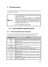
Page 40: ...mages such as B Color Power and so on The items of measurement are as follows Measure item Function Distance Measure the distance between two points on an ultrasonic image Angle Measured the angle bet...

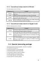
Page 41: ...sure difference at some point in the Doppler spectrum waveform are measured PS ED The velocity PS of the systolic peak point and the velocity ED of the end diastolic phase were measured on the blood f...

Page 42: ...pocket ultrasound system supports manual playback and automatic playback automatic and manual playback can be switched between each other 6 1 1 Cineloop playback The B mode and M mode cineloop will be...

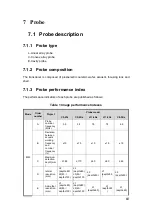
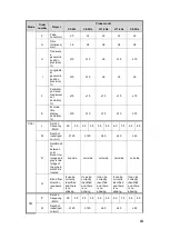
Page 43: ...ws Table 1 Image performance Indexes Mode Order number Project Probe model C5 2Fs C5 2Ks L11 4Ks L11 4Gs C8 5Ks B M A Probe nominal frequency MHz 3 5 3 5 7 5 7 5 6 5 B Deviation between acoustic worki...

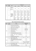
Page 44: ...M Depth of investigati on mm 120 120 40 40 40 N Relationsh ip between color blood flow image and gray scale image of the pipe in which it is located coincide coincide coincide coincide coincide O Blo...

Page 45: ...rmance Indexes Mode Order number Project Probe model E10 4Ks B M A Probe nominal frequency MHz 6 5 B Deviation between acoustic working frequency and nominal frequency 15 C Maximum detection depth mm...

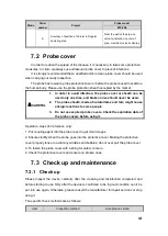
Page 46: ...2 The probe sheath made of natural latex and talc might cause allergic reactions to some people 3 Do not use expired probe covers Check the expiration date of the probe covers before using it Operati...

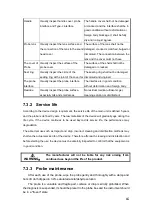
Page 47: ...y pits and small areas No residual medical ultrasonic gel cleaning solution or disinfectant 7 3 2 Service life According to the device design requirement the service life of the main unit is defined 5...

Page 48: ...ter disinfection please use sterilizing liquid to thoroughly remove the residues Chemical residue may be harmful to human body 3 If you cannot confirm the efficacy of the disinfectant solution contact...

Page 49: ...Polyurethane sponge can be used for cleaning But it is strictly forbidden to use a brush to clean to avoid damage to the handle and probe Low level disinfection The low level disinfection is only suit...

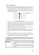
Page 50: ...or gauze or place it in a well ventilated area to let it dry completely Do not dry the probe d Check the probe carefully Only the probe that is in perfect condition can be used The specific inspectio...

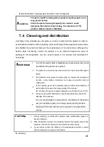
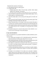
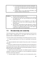
Page 51: ...e 7 5 Disassembly and assembly When the operator needs to replace another type of probe to perform a new check on the patient or replace a sterilized probe for a new patient check during operation the...

Page 52: ...isassembled equipment until it is fully dried 3 It is forbidden to put the equipment into use before it is confirmed intact 8 Puncture guide 8 1 Enter or exit puncture mode Under the Windows platform...

Page 53: ...any reports about ultrasonic cause bodily injury In spite of this we can not arbitrarily believe all the ultrasonic is absolutely safe Studies have shown that ultrasound with high intensity is harmful...

Page 54: ...tic power required to raise tissue temperature by 1 C under defined assumptions MI Mechanical index The mechanical effect is caused by the acoustic wave within the organization micro bubbles increasin...

Page 55: ...I and MI values are displayed at any operating conditions and the step value is not more than 0 2 TI display items can be set in the prefab open the image preset parameter B THI page you can see the a...

Page 56: ...Acoustic power control Sound output depends on the system operator the operator should obtain qualified under the premise of effective diagnostic image to reduce the acoustic output There are three ty...

Page 57: ...on the calculation formula is as follows 10 3 0 10 z f water atten c I I 9 7 2 Acoustic output limit In accordance with the FDA requirements of Track 3 the acoustic output limits using the derating or...

Page 58: ...introduced by the variability is bounded The sampling testing ensures that the acoustic output of transducers and systems being manufactured stays within a specified range of the nominal acoustic outp...

Page 59: ...ormal B C PW 24 544 25 261 TF 30 020 TR 4 759 C5 2Fs Still Air Normal B C PW 24 612 24 612 TF 35 528 TR 10 916 C5 2Ks TMM Normal B C PW 24 590 24 539 TF 29 08 TR 4 541 C5 2Ks Still Air Normal B C PW 2...

Page 60: ...and the need for the installation and maintenance of EMC provided in the information environment to meet the following 4 This system is lower than the minimum prescribed amplitude products or minimum...

Page 61: ...urbance guidance and manufacturer statement This system can be used in a specified electromagnetic environment users should ensure the use of electromagnetic environment in the following provisions Im...

Page 62: ...commercial or hospital environment Be careful UT is the AC voltage value before the test voltage is applied Table 3 Electromagnetic disturbance guidance and manufacturer statement This system can be u...

Page 63: ...ceiver field FM and am radio as well as TV broadcast is unable to use pure theory to accurately estimate In order to evaluate the electromagnetic environment of fixed RF transmitter generates should b...

Page 64: ...nstall the external RF transmission power noise filter the noise reduced to an acceptable level Be careful 1 In 80MHz 800MHz using a higher frequency formula Be careful 2 These guidelines do not apply...

Page 65: ...Unit 601 6 F Block B Building 1 B1 District Hantian Technology City Dongping Road Pingxi Shanghai Village Guicheng Street Nanhai District Foshan City Guangdong Province 528200 China Share Info GmbH H...

Page 66: ...aval ent chromiu m Cr VI Polybromi nated biphenyls PBB Two phenyl ether PBDE Internal wire rod LCD Button Polybromi nated biphenyls Shell Plastic cement Shield PCBA Said the content of toxic and harmf...

Page 67: ...e average sound intensity Ita z Decay time average sound intensity Izpta z Spatial peak time average sound intensity Izpta z Decay time space peak time average sound intensity MI Mechanical index P ou...

Page 68: ...33 44 Ispta at zPII or zSII mW cm 2 53 52 pr at zPII MPa 1 99 Operating control conditions Focus mm 20 20 N A 20 N A N A Depth mm 30 30 N A 30 N A N A Frequency MHz 3 2 3 2 N A 3 2 N A N A Probe C5 2F...

Page 69: ...ther Information Prr Hz 7163 8 Srr Hz 22 53 npps 1 Ipa at zPII W cm 2 23 10 Ispta at zPII or zSII mW cm 2 42 18 Ispta at zPII or zSII mW cm 2 65 74 pr at zPII MPa 1 99 Operating control conditions Foc...

Page 70: ...N A Other Information prr Hz 7163 8 srr Hz 22 53 npps 1 Ipa at zPII W cm 2 23 10 Ispta at zPII or zSII mW cm 2 44 23 Ispta at zPII or zSII mW cm 2 70 05 pr at zPII MPa 1 99 Operating control condition...

Page 71: ...m 5 13 fawf MHz 3 13 3 13 3 13 N A Other Information prr Hz 7250 3 srr Hz N A npps 1 Ipa at zPII W cm 2 57 39 Ispta at zPII or zSII mW cm 2 188 2 Ispta at zPII or zSII mW cm 2 565 5 pr at zPII MPa 3 6...

Page 72: ...zs cm N A zb cm N A zMI cm 5 13 zPII cm 5 13 fawf MHz 3 10 2 29 2 29 N A Other Information prr Hz 7162 6 srr Hz 24 959 npps 1 Ipa at zPII W cm 2 68 49 Ispta at zPII or zSII mW cm 2 66 95 Ispta at zPII...

Page 73: ...N A zb cm N A zMI cm 0 68 zPII cm 0 68 fawf MHz 7 65 7 65 7 65 N A Other Information prr Hz 4848 6 srr Hz 13 696 npps 1 Ipa at zPII W cm 2 110 23 Ispta at zPII or zSII mW cm 2 11 73 Ispta at zPII or z...

Page 74: ...m 0 68 zPII cm 0 68 fawf MHz 7 65 5 67 5 67 N A Other Information prr Hz 4848 6 srr Hz 13 696 npps 1 Ipa at zPII W cm 2 110 23 Ispta at zPII or zSII mW cm 2 49 77 Ispta at zPII or zSII mW cm 2 81 28 p...

Page 75: ...W N A N A zs cm N A zb cm 1 65 zMI cm 0 68 zPII cm 0 68 fawf MHz 5 71 5 71 5 71 N A Other Information prr Hz 4169 2 srr Hz N A npps 1 Ipa at zPII W cm 2 147 85 Ispta at zPII or zSII mW cm 2 354 11 Isp...

Page 76: ...N A Zb cm 1 70 zMI cm 0 68 zPII cm 0 68 Fawf MHz 7 66 7 66 7 66 N A Other Information Prr Hz 4750 1 Srr Hz N A npps 1 Ipa at zPII W cm 2 115 Ispta at zPII or zSII mW cm 2 204 2 Ispta at zPII or zSII...

Page 77: ...zMI MPa 1 08 P mW 13 53 13 53 N A P1x1 mW 7 91 7 91 Zs cm N A Zb cm N A zMI cm 0 68 zPII cm 0 68 Fawf MHz 7 66 5 67 5 67 N A Other Information Prr Hz 4848 6 Srr Hz 13 696 npps 1 Ipa at zPII W cm 2 13...

Page 78: ...Parameters pr at zMI MPa 1 38 P mW 6 93 6 93 N A P1x1 mW 3 83 3 83 Zs cm N A Zb cm N A zMI cm 1 72 zPII cm 1 72 Fawf MHz 6 04 6 04 6 04 N A Other Information Prr Hz 4848 4 Srr Hz 23 198 npps 1 Ipa at...

Page 79: ...Pa 1 38 P mW 13 27 13 27 N A P1x1 mW 7 33 7 33 Zs cm N A Zb cm N A zMI cm 1 72 zPII cm 1 72 Fawf MHz 6 04 4 48 4 48 N A Other Information Prr Hz 4848 4 Srr Hz 23 198 npps 1 Ipa at zPII W cm 2 91 22 Is...

Page 80: ...ameters pr at zMI MPa 1 58 P mW 20 44 20 44 N A P1x1 mW N A N A Zs cm 1 74 Zb cm 1 74 zMI cm 1 76 zPII cm 1 76 Fawf MHz 4 97 4 97 4 97 N A Other Information Prr Hz 4069 2 Srr Hz N A npps 1 Ipa at zPII...

Page 81: ...60 N A P1x1 mW N A N A Zs cm 1 75 Zb cm 1 75 zMI cm 1 65 zPII cm 1 65 Fawf MHz 5 57 5 57 5 57 N A Other Information Prr Hz 4749 9 Srr Hz N A npps 1 Ipa at zPII W cm 2 103 5 Ispta at zPII or zSII mW c...

Page 82: ...pr at zMI MPa 1 59 P mW 25 29 25 29 N A P1x1 mW 13 97 13 97 Zs cm N A Zb cm N A zMI cm 1 65 zPII cm 1 65 Fawf MHz 5 57 4 51 4 51 N A Other Information Prr Hz 4850 3 Srr Hz 23 198 npps 1 Ipa at zPII W...

Page 83: ...l manufacturer GuangDong Youkey Medical Co Ltd Unit 601 6 F Block B Building 1 B1 District Hantian Technology City Dongping Road Pingxi Shanghai Village Guicheng Street Nanhai District Foshan City Gua...

Reviews: