Page 2
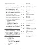
MOUNTING AND START-UP
1.
Select location for display. A location out of direct sunlight provides
best visibility.
The Wind Tracker may be mounted from a bulkhead or installed in
a flush panel by removing the mounting bracket. Panel cutout
dimensions are given in the specifications. An optional rack
mounting panel (Model WS-06280) and protective enclosure
(Model WS-06260) are available from your supplier.
2.
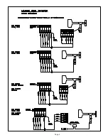
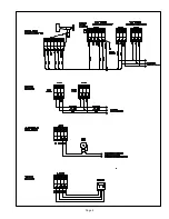
Connect cables to terminals. Refer to diagrams on page 5.
Selector switch (item 7 on back panel illustration) should be
DOWN for normal sensor inputs, UP for 4-20 mA or Wind
Monitor-SE signals.
3.
Connect GND terminal to suitable earth ground.
4.
Insert power supply plug into power jack, plug into standard AC
wall outlet.
The Wind Tracker may also be powered from ships batteries. A
coaxial power plug (2.1mm) must be used. Center is positive.
5.
The Wind Tracker will display a software version number for
approximately 4 seconds. It then begins to display wind informa-
tion. The following information is displayed:
•
Wind Speed
•
Wind Speed Units
•
Maximum Wind Speed or Direction degrees
•
Relative Wind Direction (single orange indicator)
•
Direction Variability (green indicators)
•
WS, WD Alarm Status Indicators (if selected)
6.
Observe the unit for a few minutes to verify that it is operating
properly. If you wish to change settings (ie: wind speed units). See
the following section.
CHANGING SETTINGS
The Wind Tracker has a setup mode that allows you to easily change
sensor type, wind speed units, alarm settings, and other functions.
Press and hold
ENTER
and
SELECT
keys (about 5 seconds). The
display will briefly flash “SET UP”, then begin the SETUP sequence.
Change settings with the
SELECT
key. Press the
ENTER
key to save
a setting and move to the next step. Abbreviations in the left and right
display windows identify each function and the available selections.
DISPLAY
SETUP FUNCTION
LEFT
RIGHT
Input/Sensor Type
InP
LDi
Line Driver 4-20 mA input
03
Wind Sentry
04
Wind Monitor-Jr
05
Wind Monitor, Wind Monitor-MA
SEr
Serial input from Wind Monitor-SE or main display
If SEr is selected,
wind
speed units
and
NMEA
output rate
selections do not appear.
Wind Speed Units
SPd
unt
Press SELECT to change units, ENTER to
proceed.
NMEA Output Rate
OUT
FST
16 sentences sent per second
SLO
1 sentence sent per second
Display
dSP
SPd
Displays MAXIMUM wind speed in right display.
dir
Displays WIND DIRECTION degrees
(1° resolution) in right display.
Wind Direction Alarm
ALr
no
WD alarm not used.
YES
WD alarm activated.
If no is selected, the following 2 steps do not
appear.
ALr
dir
Press SELECT to position alarm sector.
Press ENTER.
ALr
SPn
Press SELECT to set size (span) of alarm
sector.
Wind Speed Alarm
ALr
no
WS alarm not used.
YES
WS alarm activated.
If no is selected, the following step does not
appear.
ALr
000
WS alarm set point. Press SELECT to
change digits. ENTER to save.
If no alarm is selected, the following 2 steps do not
appear.
Alarm Delay Time
dLY
030
Set alarm delay time in seconds (0-999).
Sound
Snd
no
No sound with alarm.
YES
Audible beeper will sound with alarm.
Test Functions
tSt
no
Skip test functions.
YES
For troubleshooting only. YES will initiate the
following tests.
If no is selected, the unit will return to normal
operation.
tSt
Snd
Press SELECT to sound beeper.
tSt
dSP
Press SELECT to illuminate all display seg-
ments.
tSt
ALr
Press SELECT to close alarm relays.
CAL
0.00
Press SELECT to alternate between 0.00 Vout and
5.00 Vout at terminals. Use to
calibrate external
devices (recorders, etc..)
Summary of Contents for 06206
Page 6: ...Page 5...
Page 7: ...Page 6...


